Continue to Site

Welcome to our site!

Electro Tech is an online community (with over 170,000 members) who enjoy talking about and building electronic circuits, projects and gadgets. To participate you need to register. Registration is free. Click here to register now.

  • Welcome to our site! Electro Tech is an online community (with over 170,000 members) who enjoy talking about and building electronic circuits, projects and gadgets. To participate you need to register. Registration is free. Click here to register now.

Hardcode a PIC by hand? (or 16F74 + par.port.prog = problem)

Status
Not open for further replies.

smilen

New Member
(short version)

Hi all,

I had written a longer post, included below, and I am trying to shorten it now in hope to get some suggestions about my problem with programming a PIC.

I am trying to burn a 16F74 with a Tait like parallel port programmer - unsuccesfully. Used about three different programs, tried stretching the clock signals to up to 2 ms per cycle. Still nothing, it either does not write, or does not read - since it always reads $3FFF from all memory. I finally thought that I could troubleshoot using an application like VBPortTest (http://www.beyond-designs.com/download/VBPortTest/VBPortTest.htm), which allows to pulse individual pins on the parallel port by clicking on them:

**broken link removed**

So i could sort of click through a programming sequence of the 16F74. So by clicking on Data0, Data1, Data2, Data3, I would pulse Data, clock, Vdd and Vpp, and then I would see the state of Data reported back on nAck, and would know whether 16F74 is being programmmed.

The idea is then, by clicking, to raise Vpp, enter a Load data command (6 clock pulses), enter the data contents (16 clock pulses), enter Begin/End programming and then issue Read data (6 clock pulses) - and then in the next 16 pulses I should be able to read the Data pin on the nAck, and see whether the data contents have been entered. The questions are:

- Is this approach possible at all - if not why? (since specs do not specify a max time for a pulse, theoretically it shouldn't matter the prog sequence is entered slow?)

- If it is, how should I set the Data pin on the parallel port (Data0) while during the 16 clock pulses while reading - high or low - so I can read the right contents via nAck (pin 10 on parallel port?)

Basically, my biggest problem now is getting the programmer to run, so any suggestions related to that would be of great help. In that sense, I would also like to ask:

- Are there any hardware peculiarities of 16F74 that prevent me from using the Tait-like (see long post for details) parallel port programmer to burn it?
- I get Vdd=4.9V, Data/Clock high on 4.9V and Data/Clock low on 1.2V. As the specs say that low should be max 0.2*Vdd which is 0,98, and I get 1.2>0.98, could that be a reason the chip is not programmed?
- Does it matter if a programming sequence is executed very slow? Could it help resolve timing problems?
- Is the chip sensitive to how long it is kept under the high programming voltage - is it likely it could get damaged more easily?
- Is there a simple method to do a hardware check (something say involving a multimeter only :) ) and see if the chip is "alive" and what contents it would have in memory?
- Should both Vdd pins and Vss pins on a 16F74 be short-circuited to the Vdd and Gnd of the programmer, or only one each should be used (like in P16PRO40)?
- Is the LVP pin the same as the PGM pin on the 16F74? Should it be connected to ground via a resistor?
- How critical is the rise time of Vpp to the chip going into programming mode? Are there differences in how software could activate a parallel port pin from low to high, or PC software has no control over that? Or is this a matter of those parallel port modes (EPP, ECP?)
- Is there a measurable signal (say on some pin) on the 16F74 to tell if it has gone into programming mode?

For a detailed description of the situation please see the long post. Thanks for any suggestions you might have.

cheers
 
I'm about a 1/3 down your post. Just thought I'd say hello

Sorry about that :) I hoped that by giving the most info possible and asking as many questions would give some more comments about what to do next to troubleshoot the burning, but obviously it may be tedious to read all that :eek: Still hope for some suggestions, though :D

Cheers
 
Sorry but...

Too long your post :cry:

I will pass this
 
I'm rather confused by your long tale of woe?.

But basically I think the story goes somewhat like this:

1) You decide to built an existing programmer design.

2) You don't use the right IC so it doesn't work (there shouldn't be any power constraints, but the whole David Tait design is based on open-collector buffers.

3) With the right IC the programmer still doesn't work, so you then start modifying the design? - seems a bizzarre choice?, start with a known working design (which doesn't work for some reason), and then try and modify it?. It's VERY important to switch Vdd, depending on the PIC you're trying to program - entering program mode is done by various combinations of switching Vdd and Vpp - it IS possible to have a limited programmer without switching Vdd (for ICSP), but it is more limited.

If you've assembled the circuit correctly, it's reasonable to assume that the design itself is OK, there are many of them in use.

You might try using WinPicProg?, which is configurable enough to use that programmer - it gives you manual control of all the output lines, and an indication of the input line - it was done that way for just such fault finding.
 
Re: Hardcode a PIC by hand? (or 16F74 + par.port.prog = prob

smilen said:
I identified LVP as the PGM pin (pin 37) on the PIC, which is grounded wia 10K resistor, as in the schematic.
This could be the main cause of your troubles or it might be not. The PGM pin is Pin36.

smilen said:
The first problem I ran into was getting my hands on to a 7406 for the programmer, so as a starter I tried using 7405. Needless to say, the circuit behaved very strange
All the PIC programmer designs that I have seen and built does not rely on the "power handling" capacity of the chips involved. The reason of using 7406/7407 is because of its feature of open collector output. While 7405 is also open-collector, it is rated for 5V operation only so it might breakdown when 13V is applied to the open collector output. As such, the 7405 either works 100% OK or suffer damage, and will not manifest itself to show some strange behaviour. So I'm absolutely sure there was something wrong with the hardware circuit that you have built.

smilen said:
Then, with the 7406 it was better, as raising Vpp did not automatiically raise Vdd.... and you try to raise both data and clock, the circuit cannot handle this and everything drops - both Vdd and Vpp fall to about 2.5V. Apparently no programming here - whenever you try to write a 1 (data is 1 and clock gets to 1) Vpp drops and the programming gets reset.
We are talking of a digital circuit here, not an amplifier. There is no place for "better". Either it works or it don't. All these still points to hardware error in your wiring/construction.

smilen said:
The Oshonsoft programmer derives the data and clock voltages from the Vdd voltage generated by one of the transistors, whereas the Tait programmer derives these directly from the 5V source.
Yes, that could be a reason. Some designs connects the pullup resistors to +5V while some connect them to "switched" 5V. This causes difference in how the programming software "handling" the programming and so will not work one way or the other when different software is being used.

smilen said:
I guessed that this might remedy the power problem a bit, as the Vdd transisor in the Oshonsoft should demand quite some current when it's on.

A PIC takes only tens of mA or less, so power is never a problem.

smilen said:
So, I decided to set the data and clock lines to feed directly from the +5V. However, there were other problems now - whenever both Vpp and Vdd were on, as soon as either data or clock was high, Vpp turned off as in the previous case, but this did not happen when BOTH data and clock were on ?
You can only be sure that it is not the software that gives these strange behaviour by testing the hardware "without" the PC. I suggest the following procedures for anyone building such programmer:

1. Do not connect to PC and do not place PIC into socket.
2. Power up and confirm +5V and +13V healthy
3. Prepare a 100 ohm resistor and connect one end of it to +5V
4. Connect voltmeter to corresponding PIC socket pin and touch the other end of the resistor to the programmer's parallel port input pin. Watch if the corresponding PIC socket pin change from low to high or vise versa. Log the result.
5. repeat the test using one end of the resistor connects to 0V.

This would completely checks out the functioning of the hardware circuit.

Do not place a PIC in the socket yet.

The next test is to connect up the parallel cable and use the software interface "test" to check that the signal from the PC can actually controls the voltage on the PIC socket.

Now one can place a PIC into the socket and enjoy.

smilen said:
- Completely removed the Vdd switching transistor - and kept Vdd at the +5V power source at all times (thinking that it would not make a big difference since the prog spec says "VDD level for read and verification VDD min 2.0 max 5.5 V; VDD level for programming and erasing VDDP min 4.75 max 5.25 V" - so if you keep it at 5 all the time, no problem, right?)
Wrong move. The Vdd need to be controlled.

smilen said:
So here is the dead end for me :shock:
Hopefully the wrong PGM pin is all your problem.

Edited: Clearer instruction in step 4 of the testing procedure above.
 
Hi guys, and thanks very much for the replies! I have edited my post and hopefully now it is more clear what I would like to know :) I hope you wouldn't mind looking at it. Sorry about the long post, I am including it just for reference as well - it was written in desperation :)

With the right IC the programmer still doesn't work, so you then start modifying the design? - seems a bizzarre choice?

I just thought that by removing stuff and boiling the Oshonsoft circuit down to basic Tait programmer, I could have only Vpp, Clock and Data driven by software (Vdd high at all times) and thereby have a better overview over what is happening, and maybe skip over a possible timing problem? (obviously it didn't happen :) )

It's VERY important to switch Vdd
This is what I didn't know - since I assumed that it is only used to scale Data and Clock, and since I read in specs that it is OK for them to scale up to Vdd 5V even for a reading operation (just as long as you're in prog mode), i thought it would be Ok to keep it at 5 at all times :) - hoping that
it IS possible to have a limited programmer
, but maybe that is good for PICs other than 16F74?

it IS possible to have a limited programmer without switching Vdd (for ICSP)

Strictly for ICSP? Does that mean that it has to work in low programmin voltage mode?

You might try using WinPicProg
I actually did, forgot to include it :) The idea with VBPortTest should I guess be applicable with whenever manual control of the pins is possible. My question should have been originally written as: if I try to manually (by clicking the output lines) enter command and data words to program and then read back a word, should I get an indication on the input line, and how should I keep the data output while reading - high or low - so I get that indication?

Thanks again for the responses, cheers :)
 
(the long post)

Hi all,

I just recently got acquainted with PIC's, due to a project. Unfortunately, I have reached a dead point, so I hope that someone in this forum can help out. I will give out an overview of the problems I dealt with so far (apologies if the post is a bit long) - which led me, in the end, to attempt to pulse data and clock "by hand", to see if I can have a word written and read from the PIC, which is described later on in this post.

For this project, I simply have to sample the analog ins and send them out as serial code to a PC. By using Oshonsoft's demo of their PIC simulator, I could quickly compile and simulate a Basic program, which got simulated correctly - but my biggest problem is now that I cannot have it burned on the PIC. As the resources for the project are limited, I am limited to 16F74 as the only one I can get my hands on - using a home-made programmer and free software goes almost without saying.

As a starting point, after some search on the Internet, I found Oshonsoft's parallel port programmer (https://www.oshonsoft.com/picprog.html) along with the software, so I decided to build that one - mostly I am interested in the parallel port idea because I have a direct relation to which pins from the LPT are pulsing which pins on the PIC, so I thought it would be easier to troubleshoot.

Although it says in the schematic, I will note back the pin mapping from that circuit here, as I implemented them on the hardware:

Code:
LPT					PIC
D0 (pin 2)			Data (pin 40)
D1 (pin 3)			Clock (pin 39)
D2 (pin 4)			Vdd (pin 11 + pin 32 short circuit)
D3 (pin 5)			Vpp (pin 1)
ACK(pin 10) 			Data (pin 40)
GND 					Gnd (pin 12 + pin 31 short circuit)

I identified LVP as the PGM pin (pin 37) on the PIC, which is grounded wia 10K resistor, as in the schematic.

The first problem I ran into was getting my hands on to a 7406 for the programmer, so as a starter I tried using 7405. Needless to say, the circuit behaved very strange - the signals on the scope were nowhere near to being "clock"-ish and "data"-ish. Eventually, it comes out that whenever Vpp is made to rise, it automatically rises Vpp. Then I looked more closely in th 74** descriptions, and it comes out that 7406 is a hex inverter WITH a driver/buffer, whereas a 7405 is just a plain hex inverter. So, I guessed that this behaviour is probably due to the 7405 not being able to handle the power required and isolate the signals, so I put some effort and finally managed to get a 7406.

Then, with the 7406 it was better, as raising Vpp did not automatiically raise Vdd. I continued with the testing by using the VBPortTest application (can't remember where I downloaded it from - some edu site about the parallel port) which allows one to individually control pins on the parallel port, and thus control the programmer as well. Apparenly, a similar power problem occured, now being like this: whenever both Vpp and Vdd are on, and you try to raise both data and clock, the circuit cannot handle this and everything drops - both Vdd and Vpp fall to about 2.5V. Apparently no programming here - whenever you try to write a 1 (data is 1 and clock gets to 1) Vpp drops and the programming gets reset.

Here I did some more research and I found out that Oshonsoft design is basicaly a modification of the classic Tait programmer with some differences. (Actually, in the readme for Taits program fpp it says "Apart from memory size differences most flash PICs look the same to the programmer software (there are exceptions like the 16F74 - currently this program doesn't work with those)." - could that be the reason why I cannot burn the 16F74?) The Oshonsoft programmer derives the data and clock voltages from the Vdd voltage generated by one of the transistors, whereas the Tait programmer derives these directly from the 5V source. Here also I downloaded "PIC16F7X FLASH Memory Programming Specification" (30324b.pdf) from microchip.com, hoping that I would understand the process a bit better.

I guessed that this might remedy the power problem a bit, as the Vdd transisor in the Oshonsoft should demand quite some current when it's on. So, I decided to set the data and clock lines to feed directly from the +5V. However, there were other problems now - whenever both Vpp and Vdd were on, as soon as either data or clock was high, Vpp turned off as in the previous case, but this did not happen when BOTH data and clock were on ?! For some reason, then I started suspecting at the RC combination in right after D1 and D0 in the Oshonsoft version, and as they did not exist in the Tait version, I got them short-circuited. (By the way, doesn't such an RC circuit represent a lowpass filter? If so will it not slow down the rise times, which is undesireable in this application? What role would those have there then, in the Oshonsoft version, any ideas?)

Finally, then I could get individual Vpp, Vdd, data and clock on demand, without something turning on undesirably. Though, another problem occured then - when Vpp, Vdd, Clock were on and Data off, ACK would for some reason report Data on??? In order to get rid of this, I then did the following modifications to the Oshonsoft circuit:

- Completely removed the Vdd switching transistor - and kept Vdd at the +5V power source at all times (thinking that it would not make a big difference since the prog spec says "VDD level for read and verification VDD min 2.0 max 5.5 V; VDD level for programming and erasing VDDP min 4.75 max 5.25 V" - so if you keep it at 5 all the time, no problem, right?)
- Removed the LED from the Vpp switching transistor.
- Replaced the 7406 with a 7407 (thinking that the inverter + buffer combo in 7406 is more power consuming that the buffer in 7407; whereas one could deal with the inversion in software.)

Well, eventually, this helped that I get the signals that I expected, presented in this table for Vpp and Vdd high (programming mode):

Code:
par.port
pin state				voltage on PIC pins
D3	D2	D1	D0		Vpp		Vdd		clock	data
0 	0 	1 	0			13.36	4.9		4.9		1.2
0 	0 	0 	1			13.36	4.9		1.2		4.9
0 	0 	1 	1			13.36	4.9		4.9		4.9

low Vpp was measured 1.18V, low Vdd at 0 (while there still was a transistor to switch it off). Also, ACK reported correctly the state of the data pin.

However, still cannot burn the PIC. I am wandering whether this might be the reason - the prog spec says:
(RB6, RB7) input high level VIH1 min 0.8VDD
( in this case 3.92 )
(RB6, RB7) input low level VIL1 max 0.2VDD
( in this case 0.98 )

As the measured input low level is 1.2 > 0.98, could this be a possible reason for not being able to burn the chip?

As far as software is concerned, I could get these programs to drive the programmer circuit:


  • - Oshonsoft Parallel Port PIC programmer
    - WinPic - PIC programmer
    - IC-Prog 1.05D

Of course, all of them burn to the end, and then they fail verifying at adress 0000, by finding a 0000 (or 3FFF, depending on how the reading pin was inverted) instead of whatever byte that was supposed to be written. When reading the chip, it always gives 0000 (or 3FFF) for the entire memory. Well, I guess the means that the circuit either cannot read or cannot write (or both) - so I tried looking a bit closer into it.

Here is where I found WinPic very helpful, since you can run it in "slow mode (to check for timing problems)" and you can also set "extra lengthening for clock pulses (us)". I tried to run the programming in slow mode, extending the clock cycles by 2 ms, and in that way I could "catch" them on the scope. Also, I expected that in such a slow mode it would definitely have to burn the chip, if previously timing problems were the issue. So, in the end I could see really nice squarish clock and data signals, going as they are supposed to, and I could even recognize the 0110 .. 0100 ... (increment adress .. load data .. commands from the prg spec) pattern was recognizable. Here is however where WinPic is also a bit troublesome - it always burns entire memory and when the clock cycle is extended by 2000 us the burning lasts for 10 minutes or so :) (could I have burned the chip by keeping it under 13V for so long?) and once the program is over, it sends the 3FFF remains - which is also recognizable as a long "one" on the scope.

Sp, then I made a hex file that simply counted from 00 to somewhere like 5ff (couldn't type more than that), just so it stays on the scope long enough so I could see whether the same pattern is read back. And unfortunately it is not - as soon as the program starts reading back, all I can see on the scope is the long 'one' for the 3FFF being read as data, so the software is accurately reporting what it gets on the parallel port pin 10.

So, as I could not be sure whether the reading or the writing is a problem, what I tried to do is go back to VBPortTest, and try to enter a simple programming sequence to the PIC by manually clicking on the parallel port pins. The idea was to program a word in the first memory location, and then read it back. The prog spec says that for this to be done:

"The Program/Verify mode is entered by holding pins RB6 and RB7 low, while raising MCLR pin from VIL to VPP.
To enter a command, the clock pin (RB6) is pulsed six times.
Each command bit is latched ... with the Least Significant bit (LSb) of the command being input first.
The read and load commands are specified to have a minimum delay (tdly1) between the command and data. After this delay, the clock pin is cycled 16 times, with the first cycle being a START bit (0) and the last cycle being a STOP bit (0).

Issue the ‘Load Data’ command to load a word at the current (even) program memory address.
Issue a ‘Begin Programming’ command to begin programming.
Wait tprog.
Issue an ‘End Programming’ command."

So, this is what I did by pulsing the pins via VBPortTest:


  • 0. Set Vpp, Data, Clock to low.
    1. Raise Vpp (start programming)
    2. Keep Data low (first bit of 0 1 0 0: Load data command)
    3. Click to raise clock
    4. Click to lower clock
    5. Click to raise Data high (second bit of 0 1 0 0: Load data command)
    3. Click to raise clock
    4. Click to lower clock
    5. Click to lower Data (third bit of 0 1 0 0: Load data command)

etc etc keeping in mind there are six clock ticks for the command and sixteen for the data. Then, without incrementing adress, I would try issuing Read Data command, hoping that in the next sixteen clock ticks, i would see the stored word be reported back on ACK, but unfortunately nothing happened. Note however, that for this purpose I kept data low from VBPortTest - I thought that it would rise when the corresponding clock tick would arrive, while PIC is executing Read Data command.

Well, basicaly, this is what I mean by "hard-coding the PIC by hand" - I hope someone can tell me whether this is possible? For me, it has the importance of having a way to determine whether the PIC is still working, and whether the hardware is OK. Basically, the prog docs mention minimum but no maximum delays between events, so I guess it shoud be possible? I have seen on different forums however, that people mention the importance of how quick Vpp rises, in order for PICs to enter the programming mode - I have no idea whether VbPortTest would be any slower than the other apps in this regard. I have also seen discussions about the parallel port being set to EPP mode - does that have to do anything with the rise time of signals from the port? I have set my port on EPP, and I do use a laptop (which I now is not recommended - but I guess it shouldn't matter for a slow mode?).

Here is also where I noticed something: data pin (D0) was left on low during "manual" reading in VBPortTest, so it simply stayed at a low level while "reading" was going on. However, when the proper programmer software runs for reading, I always get a high level on the scope, which corresponds to the 3FFF. I guess, if I got a high level on ACK while reading, I would be pretty happy, knowing that at least I am reading the default 3FFF from the chip - but I don't. So then I checked the actual pin state of D0 at the parallel port while reading and it also showed a high state. What I don't understand is whether it is the software that keeps it high - that way, if there is a zero read on the data line, it can pull the high voltage down, otherwise it shows one (I think I saw something similar being decribed somewhere in relation to open collector design, but I don't know that means.) I think I have seen programmer software authors on this forum - maybe someone could let me know whether the high state of D0 while reading is kept like that through software?

So here is the dead end for me :shock: - I can see proper data and clock signals on a scope (at least as I would expect them) being passed to the PIC, both when reading and writing, however, as far as reading goes, 3FFF is always read back - and I don't know if this is actual high level read from the PIC or simply a feedback from a software generated high level on the D0; and eventually I do not know whether anyhing is being written or read back from the PIC at all :roll: ... and I was hoping that if I could execute a manual program command, I could be sure at least that the PIC and prog hardware are functional. But now I simply have no ideas about what to check next - so I hope someone can give me some suggestions, or point me in the right direction of how to pursue the troubleshooting further. I am thankful for any comments that would help me clear out my confusion :)

Cheers
 
Hi again, and thanks for the replies !

As such, the 7405 either works 100% OK or suffer damage, and will not manifest itself to show some strange behaviour. So I'm absolutely sure there was something wrong with the hardware circuit that you have built.

Thanks very much for this, didn't know that's how it worked ! This will definitely narrow down the possibilities of what went wrong ...

Some designs connects the pullup resistors to +5V while some connect them to "switched" 5V. This causes difference in how the programming software "handling" the programming and so will not work one way or the other when different software is being used.

Very important to know - I was unaware of this until now; I was guessing that switching the 5V is not "all that important" as switching the 13V is...

I suggest the following procedures for anyone building such programmer

Thanks so much for this! Maybe some of you guys could do a sticky post on a few methods for hardware troubleshoot of homemade programmers? I was for instance completely ignorant that :
Prepare a 100 ohm resistor and connect one end of it to +5V
- parallel port pins should be measured via a (pull-up) resistor? I always bunked the voltmeter directly to them and measured towards directly towards ground :) unlike
repeat the test using one end of the resistor connects to 0V.

tips like this are a must for anyone just starting with this stuff, thanks :)

Wrong move. The Vdd need to be controlled

Yes, I can see now it was wrong :)

Thanks for the quick responses, amasing forum !

Cheers
 
smilen said:
- parallel port pins should be measured via a (pull-up) resistor? I always bunked the voltmeter directly to them and measured towards directly towards ground :) unlike

No that was not what I meant. Sorry for causing the misunderstanding. The above step 4 amended to give a clearer meaning.
 
Did some measurements..

Hi all,

I got back to the Oshonsoft version of Tait parallel programmer that I slaughtered, and implemented the following suggestions I got here: I returned the Vdd switching transistor, and made sure pin 36 is connected to ground (just soldered it to the wronlgy connected 37, I hope that won't be a source of trouble) and I did the measurements as suggested by eblc1388 - here is what I measured (Note that I've used a 7407 in these measurements instead of a 7406):

(please see table 1)

Well, they seem to be switching OK like this, although I am not too happy about a 2.55 V low level, but well. Now the trouble comes with the LPT connected and driving the pins from a program.

(please see table 2)

And here is where the problem is, I guess - when we want to set the high voltages to all the LPT pins involved, Vpp switching transistor does not invert as it should ?! The interesting thing is, as soon as D0 or D1 go low, either of them, Vpp shows about 1.52 as it should for a high state of its LPT pin (again, just biffer from a 7407 and the transistor inverts once).

I mostly suspected the switching transistors, so I did some more measurements around them. Here is an image that I modified from the Oshonsoft schematic:

(please see circtrSwitch.png)

It is the same (apart from the base resistor) schematic for both Vpp and Vdd switches, I had removed the LED branch from both. The results are still with a 7407 (so just a buffer instead of inverter buffer):

(please see table 3)

Up to now, all looks fine - the numbers stay pretty much the same if either data or clock is turned on high. But, if *both* data and clock are turned on high, the last sitation where both Q(Vdd) and Q(Vpp) branch are driven by high LPT pins, now looks like this:

(please see table 4)

Again, it is the transistor Q in the Vpp branch that cannot stay turned off, as dictated by a high LPT pin in this case. Instead it turns on and saturates ? Also, notice that in this case Vbuf(Vdd) is 4.26 - smaller than the corresponding 4.95 when Vdd was off - but still enough to keep Q(Vdd) off. That is why the only logical thing I can think of as a reason for this, is that when all buffers try to provide a high level on their outputs, they increase the demand of the IC, and their output voltages drop slightly - which in the case of Q switching transistor for Vpp is enough to drive it into saturation (due to the higher power supply voltage). Maybe that means I have a bad IC? It is a 7406, but not necesarilly 74LS06 as demanded in the schematic. But then again, this only means that when Vdd and Vpp are low (out of programming mode) and if we set clock and data to 1, then Vpp will automatically turn on and drive the PIC into programming mode ??

So, I thought I could stabilise this by putting a bigger base resistor for Vpp, and it worked ... until I placed the PIC. Well, something most be horribly wrong here, but I simply have no idea what.. Hope some of you can give some suggestions..

Thanks for the advice so far

Cheers
 

Attachments

  • circtrswitch.png
    circtrswitch.png
    5.4 KB · Views: 985
  • table1.png
    table1.png
    6.9 KB · Views: 971
  • table2-3-4_214.zip
    29.7 KB · Views: 139
First off, it's really a VERY simple circuit - particularly when you break it down to the individual sections (like in your Vpp switching sample above).

As I'm sure you're aware, the output of the buffer pulls the base of the transistor LOW via the 4.7K, this turns the transistor ON, and supplies Vpp. When the buffer turns OFF, as it's an open-collector chip, the 4.7K resistor effectively floats, and the base/emitter resistor ensures the transistor turns OFF.

If ANYTHING else if happening?, you need to find out why - I'm also unhappy about the LOW switching voltages you mentioned?, it doesn't sound like they are really low enough?.

How about posting a picture of your programmer, so we can see what it looks like?.
 
Re: Did some measurements..

smilen said:
Well, they seem to be switching OK like this, although I am not too happy about a 2.55 V low level, but well. Now the trouble comes with the LPT connected and driving the pins from a program...... Well, something most be horribly wrong here, but I simply have no idea what.. Hope some of you can give some suggestions..

Well, you have made the obvious mistake here. Your hardware test is NOT OK and as such, all additional tests that follow would be meaningless. One does not change a schematic to make it work, unless it is horribly wrong in the first place. Usually one get it working first, then one can make improvement to it.

Instead of referring to the circuit in the webpage, I copied the circuit and added your test results.

In case of signal D1, I noticed a 100 ohm resistor already in the input of the 7407. So you should try shorting D1 directly to 0V to see if the output goes cleanly to near 0V. If the result is the still the same, 7407 is definitely faulty.

This is also the case for D0. The test result on D0 is bad too. Short D0 to 0V and confirm result. These two 100 ohm series resistors and the 1nF capacitors are only needed in case one experienced troubles in switching(ringings), so you can do without them at the moment.

Why would you get 4.51V on Vpp controlled via D3? It should be near 0V also. Measure the voltage at point Y which should be near 13V(if measured using a DVM) when you touch the resistor to 7407 input in the first test. You need to change the 10K into 680 ohm also.

Make absolutely sure that the +5V and 0V of 7407 IC and other parts of the circuit are properly connected to the corresponding supply rails. One missed connection would result in this sort of interaction between signals. Also check that you have not swapped the collector and emitter of BC557 or whatever PNP that you are using.

You must get this hardware check completed before moving on.
 

Attachments

  • picproghard3.png
    picproghard3.png
    27.3 KB · Views: 959
  • bc557_pnp.png
    bc557_pnp.png
    10.4 KB · Views: 1,057
It's working!!

Helo guys,

First of, a great THANK YOU for all your advice - had it not been for your guidance, I would have a very very hard time troubleshooting.. And finally, the circuit works, and yes, eventually it was a wiring problem :) Since I could test the PIC in a test circuit and it was running fine - I just have one question about that - I use an external 4 MHz crystal with two caps to drive Osc. I expected to see a 4 MHz signal at the ends of the crystal that go to the OSC pins in the PIC - instead I saw only some 50 Hz sinusoid (which was probably hum from the power mains) - but the PIC was working! Is this what I am supposed to get as a signal from the crystal?

Back to the programmer issue - I was going back and forth experimenting with 7407 and 7406, and in the meantime I could for a while get my hands on a graphing scope. So I could capture some of the wrong signals in two situations, with a 7407 without a PIC and a 7406 with one, the circuit being driven by a programming software - see WrongScopeSignals.png below. You can see how Vdd high turns Vpp off. You can also see how for a 7406 and a PIC the data and clock intermodulate, and one gets an almost trinary signal :)

Well, I lost the 7407 in the process, and I had to use the 7406 - so the eventual working circuit is the Oshonsoft version, without the input RC's (shorted), Data and Clock feeding from +5V directly instead of Vdd (so basically back to classis Tait), LEDs cut off, 680 Ohm used as recommended.

Generally, I have some theoretical background, but little practical experience - which is why advice like
as it's an open-collector chip, the 4.7K resistor effectively floats
is so important to me - until now, I did ignore the fact that open collector must mean that the resistor will float :) And also

the base/emitter resistor ensures the transistor turns OFF

I tend to think in terms of currents through a transistor, so I do forget sometimes about the voltages those cause :) But anyways, it was this lack of practical experience that lead to :

Well, you have made the obvious mistake here. Your hardware test is NOT OK

Basically, I thought as there is no PIC and no LPT the voltages will anyways be different from when the PIC and LPT are connected - but I didn't have an idea by how much is acceptable - so I thought as long as they switch (that is there is some high and some low voltage level that are distinguishable) then it's OK - obviously this was wrong, which is why

Your hardware test is NOT OK and as such, all additional tests that follow would be meaningless.

is a very important advice for me, that made me go back to the no PIC, no LPT check again. And it is the lack of personal experience that ade me strip elements down, so I could recognize and deal with simple stuff from theory that I could operate with - so all these mods were just to get the circuit running (as I didn't really expect the wiring to be wrong, but rather a mismatch of components). So :

Usually one get it working first, then one can make improvement to it.

I was not trying to make an improvement to the circuit - I just tried to fix it, by getting it down to something I could understand :) Maybe not the best approach, but I certainly learned a lot through it, having the guidance from this forum :)

So, what was the problem? Once I got back to no PIC, no LPT situation, I started checking the potentials around the Vpp and Vdd switching transistors, as they were the most suspicious ones. By accident I measured the end of the collector resistor (680 Ohm) of Q(Vpp) transistor was connected to ground, and I read 4.95 V ???! Of course this means that this end is actually NOT connected to ground.

In addition to not having that much practical experience, I also am a rather sloppy builder and PCB designer, which is why
How about posting a picture of your programmer, so we can see what it looks like?
made me blush with shame a bit :oops: 
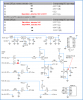
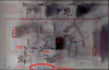
Anyways, I have included a scan (sorry for the poor quality) of the PCB. You can see that I have some very very thin tracks - the etching acid of course ate through a lot of them, so the first thing I did was to check those, and fix them with solder. As the ground line was thicker, I was not so meticulous about it - found one error there, fixed it and thought that was it.

But apparently it wasn't - so after finding these suspicious 4.95V, I checked that track again, and there was a microscopic crack in there (couldn't really see it, but I could feel it by dragging the probe lightly along the track) where the conduction stopped - so I resoldered it (the problem spot) and it started working - I could see that Data and Clock to not crossmodulated any more, and Vdd and Vpp can happily stay high at all times :) So, basically the source of the problems was a floating collector resistor of the Vpp transistor :)

So, now I could start trying out some programs. I was working on a laptop with WinXP, parallel mode set to EPP from bios (though widows Device manager still says its ECP). I tried four programs: Oshonsoft Parallel PIC programmer, WinPic, Ic-Prog and WinPicProg. From these I could burn and read only with Ic-Prog - I guess it has to do with all those Windows/Laptop/LPT timing issues: Oshonsoft couldn't neither write nor read, and it would also erase a previously programmed chip while reading (funny, as it is the Oshonsoft programmer I was builidng :) ). WinPic couldn't write or read even at very very slow rates, but it would report a few bytes different from 3FFF if the chip was previously programmed. For some reason, WinPicProg stopped raising Vpp on demand - also when you try to set it to different pins of the parallel port (a driver conflict possibly, after I reinstalled the driver for Ic-prog? - since I did use WinPicProg the previous day to pulse individual lines, and the Vpp worked fine?? ). Ic-prog could both read and write, but it was sensitive to say scope probes being put on the pins of the PIC - say, if I burn a chip with probes on data and clock, and then try to read it with only one probe, that would reset the chip, so I'd have to burn it again.

Then I tried to do the test of the PIC, so I put it in the test circuit (same kind of PCB with overetched tracks ), and I expected at least as many problems to get that one running - but this time I got lucky = worked at first - so I immediately got some serial code into HyperTerminal, so that was great.

And in the end, to answer the original question for this post - can you manually hardcode a sequence into a PIC? - yes, you can. Basically, from any prog app that allows individual line control, start by all low, then Vpp high, then Vdd high, and then you can pulse the commands - for instance, you can pulse a Read Data, and I usually set the state of the data bit first (click for change from 0 to 1, for instance), then click clock high, then clock low, then set a new bit and so on. So in the first 6 clocks enter the command word for read data (I kept the X bits on 0), and then Data has to be set high, otherwise it won't read - and then pulse the clock sixteen times = the good thing is that FF is written as 12 bits, so the first five bits (including the start bit) will be 0 (ACK high), and then next pulse, ACK will show a transition to high (reading a 1), lasting for the next 8 pulses (giving FF), and then it will flip to high (a read 0) for the stop bit. Very nice! You can even go load data (and program a word), begin programming, end programming, and reenter programmming mode, and read data - you should be able to read back the word you programmed. Though, I didn't quite get the word I entered, but then again, it is so easy to lose track of the count of your clicks :)

In any case, I would just like to thank this amasing forum for the great advice and guidance - I certainly have a better understanding of microcontroller programming now thanks to it! :D

Cheers
 

Attachments

  • wrongscopesignals.png
    wrongscopesignals.png
    385.7 KB · Views: 881
  • circ1.png
    circ1.png
    322.1 KB · Views: 907
Re: It's working!!

smilen said:
I just have one question about that - I use an external 4 MHz crystal with two caps to drive Osc. I expected to see a 4 MHz signal at the ends of the crystal that go to the OSC pins in the PIC - instead I saw only some 50 Hz sinusoid (which was probably hum from the power mains) - but the PIC was working! Is this what I am supposed to get as a signal from the crystal?

You should have a 4MHz sinewave on the crystal, you will need to use a x10 probe though, the capacitance of a x1 probe often stops the oscillator working. If you're getting a 50Hz (mains) sinewave, it sounds like you don't have the ground of your scope connected to the negative rail of the PIC circuit.

BTW, with regard to your PCB problems, WHY make the tracks so thin? - thin tracks are less reliable (as you've found out), and also cost you more because of the extra copper removed by the etching solution.
 
It great news. Your ordeal is finally over.

I hope you have learnt a lot about the tracks on a PCB one made at home. Always use the thickest track width possible to shorten the PCB etching time, to prolong the potency of the etchant and to reduce greatly the chance of any hair line cracks.

Now there are some tests that you can carry out to see whether you can improve the operation of the programmer. To start with, I don't like the two 100nF capacitors on the Vdd and Vpp connection to ground. They should not be there. One do need a 100nF capacitor at the PIC circuit board side, right next to the Vdd and Vss supply pins of the PIC but not at the programmer side. So try to remove them and you will probably find your programmer will now works with more than one software. No capacitor is needed for the Vpp line.

You can also fit back the LEDs to let you see the status of Vdd and Vpp line. These would not cause any problem.
 
Status
Not open for further replies.

New Articles From Microcontroller Tips

Back
Top