Continue to Site

Welcome to our site!

Electro Tech is an online community (with over 170,000 members) who enjoy talking about and building electronic circuits, projects and gadgets. To participate you need to register. Registration is free. Click here to register now.

  • Welcome to our site! Electro Tech is an online community (with over 170,000 members) who enjoy talking about and building electronic circuits, projects and gadgets. To participate you need to register. Registration is free. Click here to register now.

Haptic Compass Belt

Status
Not open for further replies.

Avail

New Member
Hi. I'm an electronics newbie. This is my first big project that is not a kit. I have studied some basic electronics theory but I dont know what components I should use for regulating the power with this project.

My design so far uses ATMega8 microcontroller and a HM55B compass module. It will be powered by AA cells. The microcontroller needs to be able to control eight small coin pager vibrators (Though probably only one or two at a time). The problem is that the microcontroller needs 5 volts and the motors need 1.5 volts. The microcontroller's outputs can supply up to 40mA at 5V, but the motors need 70mA.

So I figure I need some kind of active components here (e.g. transistors) to regulate the power for the microcontroller and a transistor for each motor with resistors to split the voltage. I have done some research and looked through the catalogues of some electronics suppliers and I am simply overwhelmed by the amount of components to choose from, I have no idea what to use.

Could someone suggest a good setup setup for power regulation? Also any tutorials on this issue would be great.

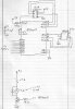
I'll try to upload some schematics tommorow, right now they are all on paper.

Thanks!
 
Last edited:
Hi Avail, and welcome to the forum!

First off, it'll be great once you get some schematics uploaded. That'll make it possible to make specific suggestions.

From what you've described so far, though, I would note that there are a million components out there but for hobbyist or student circuits, you'll usually see a fairly small subset of them used--a few commonly-used and easily-available parts can handle many tasks and make it easier for us hobbyists to chat about and share things, so we tend to use the same parts over and over.

For instance, there are lots of transistors, but for general small-signal use you would typically be looking at the good old 2N2222 (the PNP version is the 2N2907) or its slightly smaller brother the 2N3904 (PNP: 2N3906). The 2222 can handle more power and the 3904 is slightly faster, but for general low-power switching or amplification use either will usually do. As you build more kits and read more stuff you'll start to recognize the same parts (or families of parts) over and over.

You say you need 70mA per motor. You'd allocate one transistor per motor, so in this case either the 2222 or 3904 would easily handle the task. I'd probably start by putting a 1K resistor between the transistor's base and the µC's output, grounding the emitter, and putting the motor between +V and the collector. I don't know if it's necessary with such small motors but I would suggest a protection diode across the motor.

Do you know the motor ratings? That would help. And it'll be easier to give a better answer once the schematics are posted.


Anyway, good luck!

Torben
 
Another option might be to use a ULN2003 chip which can drive 7 motors, or ULN2803 which can drive 8 motors, they are a very simple chip to use; just connect directly between the PIC pins and the motors, although you may need a series resistor for each motor.
 
Here is the motor I want to use:

**broken link removed**

It is the first one on that page.

I have been looking more closely at that motor. It says its rated at 1.5V and is 7 Ohms, but at 1.5V it should be using about 20mA of current, not 70? If the 7 Ohms correct then I should be able to use it with the output from the ATMega8 with just a resistor in series right? I suppose I would still want the diode in parallel with each motor so it doesn't fry the chip?

I still need to figure out how to have a regular 5 volts for the chip, even if the input voltage drops as the batteries discharge.

I have attached the schematic of what I have so far.
 

Attachments

  • belt.jpeg
    belt.jpeg
    91.8 KB · Views: 276
Status
Not open for further replies.

Latest threads

New Articles From Microcontroller Tips

Back
Top