Continue to Site

Welcome to our site!

Electro Tech is an online community (with over 170,000 members) who enjoy talking about and building electronic circuits, projects and gadgets. To participate you need to register. Registration is free. Click here to register now.

  • Welcome to our site! Electro Tech is an online community (with over 170,000 members) who enjoy talking about and building electronic circuits, projects and gadgets. To participate you need to register. Registration is free. Click here to register now.

H-bridge output detection: rectifier issue

Status
Not open for further replies.

earckens

Member
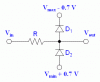
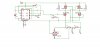
Hi, the purpose of this circuit is to detect whether there is a short across lug P6 and lug P7. Therefor a square wave is sent across a H-bridge load, part of which are the sensing lugs P6 and P7. If there is no short, the voltage across the bridge is placed over the 1M resistor part, if this resistor is shorted, the bridge voltage is placed across the 1k resistor.

Since the H-bridge output is an alternating square wave, this needs to be rectified (I need a rectified output, either 12V or approx 0V since this is fed into a controller input that expects either HIGH or LOW).

When the 1M is shorted, a nice DC 12V appears across the rectifier outputs.

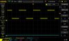
However, when this short is removed, the voltage does not drop to approx. 0V (the 1M/1k voltage divider result): a square wave (with H-bridge frequency) appears, min. 2V, max. 12V, see picture.

How can this be resolved so that shorted lugs will result in approx. 0V on the rectifier output?

EDIT: the AC input of the rectifier (measured across the AC pins) is a square wave from -12V to +12V when the lugs are shorted. With open lugs there is 0V.

EDIT2: or should an optocoupler get involved?
 

Attachments

  • DS1Z_QuickPrint38.jpg
    DS1Z_QuickPrint38.jpg
    75.5 KB · Views: 98
  • electrotechonline.jpg
    electrotechonline.jpg
    131.9 KB · Views: 90
Last edited:
You could replace the resistive divider and rectifier with rail clamp diodes and a current limiting resistor.

That will let your square wave dip to 0V.

But the reason your rectifier gives a square wave rather than a steadyish DC output voltage is because an input to the rectifier is always grounded (via a MOSFET) and an output to the rectifier is always connected to ground. It's basically just being a diode in that case, not a rectifier.

You can't have a straight current path from the output of the rectifier run right back to one of the inputs.

Tossing a non-polarized DC-blocking capacitor onto each input of your rectifier might work (I didn't think it through too carefully but it's easy enough to try). Your H-bridge just has to stay active and at sufficiently high frequency to keep the AC going through the cap for it to work becuase you know...DC-blocking cap. The lower the frequency the larger the cap has to be.
 

Attachments

  • jyZvD.gif
    jyZvD.gif
    2 KB · Views: 82
Last edited:
You could replace the resistive divider and rectifier with rail clamp diodes and a current limiting resistor.

That will let your square wave dip to 0V.

But the reason your rectifier gives a square wave rather than a steadyish DC output voltage is because an input to the rectifier is always grounded (via a MOSFET) and an output to the rectifier is always connected to ground. It's basically just being a diode in that case, not a rectifier.

You can't have a straight current path from the output of the rectifier run right back to one of the inputs.

Tossing a non-polarized DC-blocking capacitor onto each input of your rectifier might work (I didn't think it through too carefully but it's easy enough to try). Your H-bridge just has to stay active and at sufficiently high frequency to keep the AC going through the cap for it to work becuase you know...DC-blocking cap. The lower the frequency the larger the cap has to be.
Well the operating frequency will rather be low (<50Hz), but I may reconsider that requirement. And indeed thank you for your explanation, I had been thinking in circles about this issue.

Meanwhile I had been thinking about introducing an optocoupler: see attached schematic. Your explanation proves that using a rectifier grounded to the H-bridge ground is not a good idea; electrically isolating the signal from the circuit ground may give me what I need: either high for high liquid level, or low for low liquid level. The rectifier is not coupled to an H-bridge supply or ground line, it rectifies what I need, and its output drives the optocoupler either on or off. What is your opinion?
 

Attachments

  • zwembad niveaudetectie v2.jpg
    zwembad niveaudetectie v2.jpg
    194.3 KB · Views: 81
That should work except that you need a current limiting resistor in series with the optocoupler input so the LED doesn't burn out.

I'm also not sure how bad the blips will be on the output signal whenever it changes polarity so you might want a low-pass filter on the output of the rectifier (but before the LED current limiting resistor) to smooth that out.
 
Last edited:
That should work You need a current limiting resistor in series with the optocoupler input so the LED doesn't burn out.

I'm also not sure how bad the blips will be on the output signal whenever it changes polarity so you might want a low-pass filter on the output of the rectifier (but before the LED current limiting resistor) to smooth that out.
Great! Thank you for that info. Tomorrow I will do some breadboard testing and scope measurements, results will be posted.
 
Actually, if you want to minimize blips then you probably need a straight up zener in parallel the LED, oherwise the current sense resistor will have to be large enough to limit current through the LED at peak voltage but that means that lower voltages won't be able to turn it on. With a zener clamp, the current limiting resistor could be be smaller to let the LED turn on a lower output voltages which will minimize how long it stays off during the blip. The resistor also has to be sized such that it limits the current in the zener so it is able to survive at peak voltage or a zener that can handle more current can be chosen),

That would also let you make your low-pass filter not be so low pass since there is not as much to smooth out so that it responds faster. You might be able to do away with the low-pass filter in some cases.
 
Last edited:
Actually, if you want to minimize blips then you probably need a straight up zener in parallel the LED, oherwise the current sense resistor will have to be large enough to limit current through the LED at peak voltage but that means that lower voltages won't be able to turn it on. With a zener clamp, the current limiting resistor could be be smaller to let the LED turn on a lower output voltages which will minimize how long it stays off during the blip. The resistor also has to be sized such that it limits the current in the zener so it is able to survive at peak voltage or a zener that can handle more current can be chosen),

That would also let you make your low-pass filter not be so low pass since there is not as much to smooth out so that it responds faster. You might be able to do away with the low-pass filter in some cases.
The CNY17 needs about 40 to 50mA to drive the output transistor in saturation. The rectifier output is either 0V or 12V (sensor supply line). I noticed pulses less then 1usec both at low sensor output as well as high sensor output: I assume these are bridge MOSFET transition pulses; they disappear when I add a 1uF cap to the rectifier output.
A zener diode as you suggest may then not be necessary?

As an added request, I would like the rectifier output filter sensor transitions from L->H or H->L of less than about 1 second: how would that best be accomplished in hardware?
EDIT: in effect ignoring anything of less than this time, something like a low pass filter maybe?
EDIT2: I am so sorry: this question has already been answered in the "Pulse duration detection" topic.
 
Last edited:
The CNY17 needs about 40 to 50mA to drive the output transistor in saturation. The rectifier output is either 0V or 12V (sensor supply line). I noticed pulses less then 1usec both at low sensor output as well as high sensor output: I assume these are bridge MOSFET transition pulses; they disappear when I add a 1uF cap to the rectifier output.
A zener diode as you suggest may then not be necessary?

Yes.
 
Status
Not open for further replies.

Latest threads

New Articles From Microcontroller Tips

Back
Top