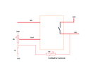
I want to control a DC motor in both directions controlled by a forward and reverse relay. I need to monitor a select-able and adjustable AC Current in the range of 5A to 50A.
Lets say I select and set 20A. If the current is lower then 20A, the forward relay will energize the motor until the current goes up to 20A. If the current goes over 20A , the reverse relay will energize the motor until the current drops back to 20A. The motor is driving a variac (variable transformer). The motor is slow and will not really overshoot. The current change is also very slow. The hysteresis should be not larger then 1.5A If the control is de-energized, the reverse relay contacts will be closed and the motor will run from the separate power until a limit switch stops it. If the control is energized there will be 0 AC current and the forward relay contact will close and drive the motor until it reaches 20A. Of course the reverse relay contacts will open. The supply voltage is 120V 60Hz. I do have 100A CT.
So I need to figure out how to convert a variable AC current reading (by CT) into a positive or negative signal to control the motor direction relays.
I am hoping there are some electronic modules which can be adapted. For example, I used a $10 temperature control module (AliExpress) with build in timer and adjustable hysteresis to dampen reaction, substituted the temperature sensor varistor with a light sensor. Then I had a light-control unit for street lights which can be very precisely set , we are saving about 2 hours running time per day. In my case a -15C is the perfect switching point for dawn and dusk.


