Continue to Site

Welcome to our site!

Electro Tech is an online community (with over 170,000 members) who enjoy talking about and building electronic circuits, projects and gadgets. To participate you need to register. Registration is free. Click here to register now.

  • Welcome to our site! Electro Tech is an online community (with over 170,000 members) who enjoy talking about and building electronic circuits, projects and gadgets. To participate you need to register. Registration is free. Click here to register now.

h-bridge help

Status
Not open for further replies.

phobos

New Member
I am havening ruble finding a H-bridge ic that can handle the amps to run a 14.4v drill motor. I would prefer to be able to get free samples. Thanks for any help.
 
If you cannot find an integrated h-bridge for your needs (high current) you can build one from 4 N-channel MOSFETs and a H-bridge mosfet driver IC like for example HIP4082 (Intersil - they have also appnotes for using this IC). This way you are mainly limited by current the MOSFETs are able to handle.
 
I don't know the current is rite now I'm trying to find out the cost, I have vary little money for these protect.
 
you cannot design your h-bridge without knowing the current. You should know both normal operating current of the motor and also the stall curent (which can be significantly higher). You can try to measure it if you don't know the current.
 
I am a newbie...

Hi..

I wanted to post a new thread but cannot cos I'm new here, so hope you don't mind i post here?

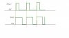
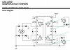
I am using this L293 H-bridge to drive my DCmotor. From the attachment, lets say my circuit is similar to that, the left motor. The ENABLE pin 1 is on, and i've PWM of 30% on, 70% off, into pin 2. The inverted 30% off, 70% on into pin 7. The 2nd attachment shows my outputs (are they wrong? should they be mirror image?).

But I do not understand how this works. The DC motor only rotates when either 1-0 or 0-1 at the 2 outputs? And whether its 1-0 or 0-1 determines its direction of rotation?

If the 2 waveforms are mirror images, then the motor rotates in direction A for 30%, then rotates in opposite direction for 70%, and so on?
 

Attachments

  • 2waveform at dc when clicked start.JPG
    2waveform at dc when clicked start.JPG
    12.4 KB · Views: 275
  • L293 H-bridge.JPG
    L293 H-bridge.JPG
    36.2 KB · Views: 383
Status
Not open for further replies.

Latest threads

New Articles From Microcontroller Tips

Back
Top