Continue to Site

Welcome to our site!

Electro Tech is an online community (with over 170,000 members) who enjoy talking about and building electronic circuits, projects and gadgets. To participate you need to register. Registration is free. Click here to register now.

  • Welcome to our site! Electro Tech is an online community (with over 170,000 members) who enjoy talking about and building electronic circuits, projects and gadgets. To participate you need to register. Registration is free. Click here to register now.

H-Bridge Help

Status
Not open for further replies.

anita1984

New Member
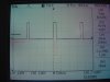
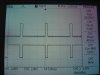
I am building a H-bridge to control motor in forward mode and reverse mode , in the attachment i draw the schematic of the circuit , my problem is that the output signal looks like in the picture DSC07167 black signal and i need it like the red signal. How should the input signal of 2 PWM to have on the ouput the both mode? my inputs(before logic gates signals) are in the picture DSC07168
Thanks in advance,
 

Attachments

  • H-Bridge.jpg
    H-Bridge.jpg
    26.5 KB · Views: 147
  • DSC07167.JPG
    DSC07167.JPG
    125.8 KB · Views: 141
  • DSC07168.JPG
    DSC07168.JPG
    123 KB · Views: 144
I didn't really understand your question, but it looks to me as though both of your inputs are connected to the same signals. You should use one input for forward motion and the other input for reverse motion.
 
My output is wrong , i need it like i draw it in the RED , both signal are connected to the logic gates to protect the h-bridge from any signals with logic 1 1 and 0 0
 
I still think you're driving your bridge wrong, but I might just be misunderstand what you're saying.
 
just looking the schematic over, it looks correct. I think it must be your input signal.
 
You need three states of the two signals "pin4" and "pin5"; 00 or 11 to stop the motor, 01 to run one way, and 10 to run the other way. Another way to say this is that only "pin4" or "pin5" should be driven to cause the motor to run...

Your traces show you driving "pin5" with the complement of "pin4".
 
Last edited:
Another way to say this is that only "pin4" or "pin5" should be driven to cause the motor to run...

I want only two modes , forward and reverse , and i don't want the 11 and 00. how i can drive this schematic with only one Pin : Pin4 or Pin5 , it's not duable by only one Pin. Please explain for me more(by picture if it's possible) , maybe i understand it in another way.
Thanks in advance
 
Don't you have to turn off the drive to the motor, let it coast to a stop, before reversing it?
 
I want only two modes , forward and reverse , and i don't want the 11 and 00. how i can drive this schematic with only one Pin : Pin4 or Pin5 , it's not duable by only one Pin. Please explain for me more(by picture if it's possible) , maybe i understand it in another way.
Thanks in advance
The motor will never stop?
 
I think I would add some resistors from base to emitter on output devices to ensure they are turned off and not leak.
 
I'd trash the nand gates, use a low on the left invertor for one direction, low on the other for the reverse direction. Both high for stop, and never apply lows on both inputs.
 
Status
Not open for further replies.

Latest threads

New Articles From Microcontroller Tips

Back
Top