Continue to Site

Welcome to our site!

Electro Tech is an online community (with over 170,000 members) who enjoy talking about and building electronic circuits, projects and gadgets. To participate you need to register. Registration is free. Click here to register now.

  • Welcome to our site! Electro Tech is an online community (with over 170,000 members) who enjoy talking about and building electronic circuits, projects and gadgets. To participate you need to register. Registration is free. Click here to register now.

h-bridge fet transistors ?

Status
Not open for further replies.

breadboardguy

New Member
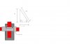
I need to build a h-bridge for my mobile breadboard (aka hammerhead cause of its shape).
I did all the schematics with some features like all inputs high impossible(so no short) but as i am a newb ... some discoveries got me a new question:

**broken link removed**

In my drawings i only used n-channel irf511 to source the motor and to complete the circuit (to the - terminal of the battery) but on that website, two type are use (npn and pnp).

Will i be fine to use only the irf511 on my robot?
(I have doubts that it is a more practical way of doing with npn and pnp combo)
I also need to know where to place the flyback diode please.

Thank you (if you post of course).
 
Last edited:
You can easily use all NMOS fets, though you will need a bootstrap cap and diode on the high side drivers.

Place the freewheel diode as close to the motor as possible. Right on the motor if you can.

Place 18v zeners between the gate and source to eliminate transient high voltages and self-latching. Also place a 100pF ceramic cap between the drain and source of all the mosfets. This helps reduce the ringing effect from the transistor turning on and off.
 
Last edited:
By freewheel diode, do you mean fly back diode?

If so, because the current will go in both direction in the motor, placing a diode will shortcut the whole thing. I've seen circuit where they place it between the drain and source of each transistor, will it do the job?
 
Last edited:
Sorry, was braindead on the diode. Was thinking single direction, even though you obviously said h-bridge. I blame lack of coffee. :)

Yes, place them on the drain and source of each mosfet.
 
Take a look at this **broken link removed**

It has source to drain diode built in for inductive loads.
 
Last edited:
Take a look at this **broken link removed**

It has source to drain diode built in for inductive loads.

The built in diodes of mosfets should not be used as a freewheel diode. They are an artifact of the manufacturing process, and not put there specifically. If you use them as freewheel diodes, they can cause huge turn on delays, and could even blow the mosfet.

They are part of the mosfet, and in use when the mosfet is forward conducting.
 
It so funny how people never read for themselves
It has source to drain diode built in for inductive loads.
That's what the maker said not me so leave me out of it.
It didn't say this
artifact of the manufacturing process
any where in the data sheet Not all fets are the same and yes some come with diodes built in not "artifact"
and some come all ready for use with 5 volt Uc just plug and play
 
Last edited:
If you read the actual datasheets on the product, nowhere does it say the body diode should be used for inductive loads. That is probably just something added by the creator of that web page.

Read these app notes from International Rectifier and Fairchild about mosfets...

They both say using the body diode for inductive current can blow the fet. Sure, many people get away with it, but why take the chance when a simple schottkey is much better at the job anyway. It gets even worse if you are in an h-bridge configuration.
 

Attachments

  • AN-IRF on Mosfets.pdf
    92 KB · Views: 400
  • AN-Fairchild on Mosfets.pdf
    352.7 KB · Views: 390
Last edited:
Nope the man that quoted it on his web site is right it tells in the data sheet read it's on the first page here a quote
 

Attachments

  • 511.pdf
    74.9 KB · Views: 354
  • fet.PNG
    fet.PNG
    20.7 KB · Views: 582
Yes, but it says nothing about using it for inductive loads. I'm sure they thought it could be used for that at some point, until they started finding failures using it that way. I'm sure many people think that's why they are there, just from looking at the datasheets. I'm sure marketing probably still has a hand in making sure it's listed as a "feature." And many people get away with using them in that way; you could even design for their use if you take the time to.

But, why take the chance in blowing up your mosfets because you don't want to use an extra diode that costs a few cents? That just seems silly to me.

Read the app notes. They are incredibly enlightening.
 
It dose say
It has source to drain diode built in for inductive loads
But that wasn't even the point. The Point is you need them and if it doesn't have them you better add them yourself. And the nice little pic shows where it would go if not there.
 
Hi,


I can add a little information here...

I can state that it is a fact that there are many power converters out there
that do not use an 'extra' diode in parallel with the MOSFET, and depend
entirely on the integral body diode to take care of the back emf of any
inductive loads. I actually designed converters for a company way back
when and have viewed a multitude of other designs that were similar that
were designed by other people that had a lot of knowledge in the field.
The converters ranged in power from 500 watts to about 10,000 watts
(not all were MOSFET designs however).

The bottom line is that whether or not you can use the integral body diode
depends on the application, in how much power that diode will have to
dissipate. If you look on any data sheet you will find that that particular
diode has a rather high forward voltage, much higher than an external Schottky
would have for example. This means that the transistor using the internal diode
has to dissipate an extra amount of power, not only while the thing is in
conduction, but also when the diode is in conduction, which increases the total
power dissipation of that one little package (even if the forward voltage of
the internal diode wasnt higher than normal). This is probably the biggest
factor in determining if you can use the internal diode or not.
Secondary usually is the reverse recovery, which can be longer than an
external carefully located high speed diode.

The extra power dissipation has to be carefully examined relative to the application.
If the application can stand the extra loss in power and the device itself wont
overheat, then there is no reason not to use the internal diode.
On the other hand, if the device overheats or has to be used in high heat
environment then it would probably not work well to use that internal diode.

Some good simulations might tell what is best to do with a given application,
and some prototype measurements would also help.

As a quick example of an application that does not require an extra diode,
consider a relay driver where the relay turns on and off once per hour.
The integral body diode sees a current spike once per hour that lasts
probably 1ms or maybe even 10ms, but after that it has almost 60 minutes
to cool back down. Adding an extra diode would really be silly here.

On the other hand, a very high speed H bridge may benefit from adding
extra diodes because doing that, if not anything else, moves some of the
heat out of the transistor package and therefore keeps it cooler.
A careful analysis has to be made and some prototype measurements
would verify the need for any extra diodes.

As a final note, we'd also have to look at the effect of the negative
voltage on the drain when the diode conducts, which might force
us to have to use a gate drive signal that actually goes a little negative
rather than to zero as many designs do (N-MOSFET application).
 
Last edited:
Thank you evryone to had answered my questions so fast, electro-tech-online really is a great community. However, i have a geometry question that is burning my lips but i only see my father in two days... so i hope you can answer me (i'l be happy):

To get my h-bridge to move, i need sensor, mine is a ir sharp range finder on a servo motor ( i might also make a version with an lcd screen and sonar range finder to see in total dark) the range finder moves of 1 degree, takes the range of the object in front of it and repeat, like a sort of sonar. this makes a virtual map of the robot environement and he knows if he fits in a corridor or need to make some exercises to move around.

The problem is that (obviously) geometry is involved and i dont have very advanced notions ( i am 14 after all ) and... i need to know how to measure the ??? segments , while i know the x segment and y angle in a formula so i can load it in the pic 18f2525.

(that way i can set a particular bit on the virtual map( the map is 15 bit long and 8 bit high, more if i get my hand on a 1024 channel adc and sonar)).

help would be really appreciated.
 

Attachments

  • irrange.JPG
    irrange.JPG
    20.7 KB · Views: 399
Status
Not open for further replies.

Latest threads

New Articles From Microcontroller Tips

Back
Top