Continue to Site

Welcome to our site!

Electro Tech is an online community (with over 170,000 members) who enjoy talking about and building electronic circuits, projects and gadgets. To participate you need to register. Registration is free. Click here to register now.

  • Welcome to our site! Electro Tech is an online community (with over 170,000 members) who enjoy talking about and building electronic circuits, projects and gadgets. To participate you need to register. Registration is free. Click here to register now.

guidance with op-amp bandpass filter, help!

Status
Not open for further replies.

Therion

New Member
Hey guys – this is my first post, as im just starting a new electrical project..
I am not overly comfortable with electrical basics, the purpose of this being to further my understanding...

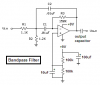
Im basically attempting to build a bandpass op-amp filter.

I have basically decided to base my design around the 'Single Op-Amp Bandpass Filter' found here..
**broken link removed**

I’ve just got my head around discerning the values of the resistors, and how they denote the frequency cut offs of the filter.

The design is for potentially for an outboard effects rack for use in post production in an audio studio.
Due to this I understand theres to be considerations concerning accepting line level, and spitting out line level, but am unsure how to design these input/output stages, concerning the standard impedances of the connected equipment..

Powering is also a gray area for me, as I am unsure how to incorporate the 9V battery I am hoping to use. At the moment I have the positive pin connected to the first input resistor, and the negative to ground, is this correct?

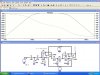
This is all being designed in Edwin at the moment, which is also presenting a steep learning curve for me, I will happily add a screenshot if you guys think it’d be helpful.

I am also unsure how Slope per octave (order etc) of the filter is designed within the filter itself. Any advice would be greatly appreciated!

The view is to eventually build the device, with possibly extra sections being added such as a potentiometer gain control, or tonal controls, although im aware this will require a lot of extra work, so for now, I just want to build a working input/output model that can be simulated within Edwin.

Thanks in advance for taking the time to read this post,
Any guidance or advice would be very gratefully received..
If theres anything else I can clarify, I will happily try!

Thanks again,

Rob
 
Rob, look at the last circuit diagram in your reference. It shows that power to the LM1458 (?) op amp connects to pins 4 and 8. All op amps have designated power pins. Be sure to use correct polarity.

The other circuits above show + (non inverting) and _ (inverting) amplifier inputs only and not power supply connections. These are signal inputs, not power.

The - input is used for negative feedback from the output terminal via a resistor and I think is shown and discussed in the other circuits shown in your reference.

I recommend you google "band pass op amplifier design" or something similar and do some more reading. Try to find some bandpass designs to study.

Hope this helps a bit.

Jess
 
The circuit that you attached assumes you are powering it with a positive and a negative supplies. It can be powered by a single 9V battery if you connect it like this:
 

Attachments

  • Bandpass Filter.PNG
    Bandpass Filter.PNG
    6.3 KB · Views: 434
ahhh thanks for your help guys, much appreciated!
yes, thats where i got confused, i was working from the second circuit on the page, that had no power specified.. i've input into Edwin the opamp that displays these power terminals..

so in your examples audio guru, the inverting single supply seems to be most viable for me.. those two 12V designations, can both be connected to a single 12V power rail?

im not quite sure how to utilise testing within edwin, as i assume i will need to also specfify an input voltage, aswell as the powering voltage, in order for it to have a signal to manipulate. Would this be done with a sine generator? how would i define this, as a voltage, or a frequency?

thanks again for your speedy help guys!

Rob
 
Keep in mind that the source impedance is to be added to R1 but if the source is another op amp, the source impedance will be low enough to neglect. BTW, what are the bandwidth requirements of the filter? A bandpass filter can be stagger tuned for a limited range but for wider bandwidth, using lowpass - hipass filters are best. If you Google you may find a program to design the filter, it is not a simple task.
 
The points marked "9V" in my schematic are the same power supply connection and can be 12V instead if you want.

This bandpass filter passes mainly a single frequency and has steep slopes at its peak frequency then the slopes became less steep at frequencies away from the peak.

Feed it with a sine-wave to test it. The amplitude of the input signal must be reduced at the peak frequency because this filter has gain at its peak frequency.
 
thanks again for your quick replies..

Russlk, so the output impedance of the source is theoretically added to the input resistor? to give the true input impedance?

It is for use in an audio situation, so i need it to be able to accept 'line level' and output also at that level, having had the bandwidth modifyied.. would a zero gain voltage follower be the best way to achieve this?
im looking to get a passband of around - 60Hz to roughly 15kHz, i see theres a formula for calculating the bassband, with use of resistors, readily available.

From what audioguru says, it seems the filter i'd given wont be nessacarily the best bet, as really im looking for as flat a response as possible within the passband itself.

do you think maybe the route of separte high pass - lowpass filters, followed by a 'makeup' gain opamp might be, a better way to approach this then?

i was also looking to push the opamp into soft clipping - is this utilised by pushing Voltage saturation value for the opamp? this is really only a slight afterthought, i really just want a working bandpass line in, line out, filter opamp, with which i can start to interchange componets..

thanks again guys - cannot say how useful this is to me!
 
You need a lowpass filter, followed by a high pass one - a bandpass filter using a single opamp would have nowhere near the bandwidth. There should be no need for an extra amp to add extra gain, in the passband the gain should be one anyway.

I'm also bemused by your reference to 'soft clipping' - if you over drive an opamp it will sound truely horrible - you could add a soft clipping stage if you wanted, but it sounds a fairly bizzare idea?.

Perhaps you should try telling us what you're trying to do?, the filter idea seems a bit strange as well really?.
 
hey - thanks for the clarification nigel.. i'll definately approach it via low-pass, high-pass design route..
sorry if im being ambiguous - essentially im hoping to use it as a post-production tool for audio engineering, the idea being to modify a mono audio signal from a jack input, being fed from another standard piece of audio equipment, hence line level considerations, and modify this to an almost 'telephone' like bandwidth, but much less radically, really i want to take out just enough of the high and low frequencies to make it noticeable but not overbearing.
the soft clipping was just an extension upon the sound im trying to achieve, but, lets not worry about that now!
sorry if i've left anything out, hope its a little clearer.
so your saying, two active filter opamps in series would do the job?
thanks again
 
Therion said:
sorry if i've left anything out, hope its a little clearer.
so your saying, two active filter opamps in series would do the job?
thanks again

Yes, that's all you need - and, as suggested, depending on the input and output impedances, unity gain buffers might be a good idea.

However, I would suggest your proposed bandwidth 'limiting' is going to be pretty well inaudible.

I hesitate to complicate matters? - but using a variable low pass filter, followed by a variable high pass filter, will allow you alter the bandpass to give the effect you want. Probably the easiest way would be to use switched capacitor filters - a quick google will explain what they are.
 
Telephone bandwidth is supposed to be 300Hz to 3kHz. But when I worked with telephone systems I was horrified to measure 3kHz at 12dB down. The spec limit is -7.5dB to the central office plus another -7.5dB from the central office to the distant end for a total allowable loss at 3kHz of 15dB!

Don't tell the telephone company but I made and installed many audio equalizers for boardroom tele-conferencing systems that had a 10dB peak at 3kHz. They sounded very crisp and clear. Each one I demo'd was sold.
 
Yes, you should add the source impedance to the input resistor, Probably 600 ohms in this case. Nigel is right, high pass - low pass filters are needed for such a wide bandwidth. But as Audioguru pointed out, telephone bandwidth is much narrower than 60Hz-15kHz. The Sallen-Key topology will fit your needs, the gain is unity and Butterworth or Tchebychef response can be obtained from tables.
 
hey guys, sorry i've been out for awhile, i've been beavering away trying to make this happen! your community input has been invaluable so far, so again thanks! i've just about got my circuit to simulate in edwin, and i have the frequencey response i wanted :D although im having problems with it, largely the amplitude of the output signal.
The most i seem able to squeeze out is around -80dB, even with a secondary makeup gain op-amp, i still only get about 60. If anyone could cast their eye of the circuit for me, that'd be massively appreciated. The vgen is setup to output half a volt, as per line level, and it says theres 2.7 volts at the output, but the amplitude is still so low. somewhere the current seems to be getting lost! still not sure about the practical implications of the circuit, like, whats going to happen when its connected it equipment at the I/O stages.
again, any advice would be massively appreciated, thanks for reading!
**broken link removed**
 
Your opamps have way too much gain.
The first opamp has a gain of 500.
The second opamp has a gain of 250.
The third opamp has a gain of 500.
The total amount of gain is 62.5 million which is rediculous.

The lowpass filter cuts frequencies above 107Hz.
The highpass filter cuts frequencies below 80kHz.
Completely wrong! Almost no sound gets through.
 
i realise the op-amps are being pushed way to hard, i was looking to try to see how much i could get out of them, before i realised there must have been a mistake somewhere. so how come with such a high gain, and standard input level am i getting next to nothing at the output?
according to my calculations, and edwins simulation, the frequencey cut offs i have are correct, with the LP cutting at roughly 2kHz, and the HP cutting at roughly 100Hz, which is the passband i'd wanted.
are my calculations that wrong? any help in discerning where the power loss is occuring, would be truly appreciated..
 
What are the dotted lines? They appear to denote circuit traces (???). If so, Res 8 and Res 14 are tied together bypassing (shorting out) OP amp 3?

Also, the amplitude curve shows a max gain of -87db which is an attenuation of 87db.

Are the voltages listed, 2.7V, a dc or an ac voltage? You should be interested in the ac voltages for gain calculations.

I am not familiar with "Edwin". Is it a simulator and free or commercial. A source reference please.

Jess
 
Last edited:
Your calculations for the filters are wrong. Their frequencies are backwards.

You want 625Hz to pass but the lowpass filter cuts it 14db.
The highpass filter cuts 625Hz 42dB.
The total cut at 625Hz is 56dB so the output is nearly 1/1000th. The filters have opposite phase shifts that cancel the signal and reduce its level even more. -87db is less than one part in 20 thousand.

Those are the simplest filters known to man (and woman?). There is not a flat section. Use 2nd-order Sallen and Key Butterworth filters for a flat section and sharper cutoffs.
 

Attachments

  • lowpass and highpass filters.PNG
    lowpass and highpass filters.PNG
    6.8 KB · Views: 208
Those 3rd-order Butterworth filters do a very good job. They don't have any loss in the bandpass and their corners are sharp.
 
Hey guys thanks for the input, it is greatly appreciated.
Im sorry if my lack of electrical education is exacerbating matters,
Hopefully, I’ll get there in the end.

Edwin is an electrical schematic and PCB design package from visionics, unfortunately, it does cost..
Info at.. http://www.visionics.a.se/

I was lead to believe it’s the industry standard, and the best to use.
Yeah Jess, those dotted lines are supposed to be ‘nets’ that indicate the actual wiring of the circuit, so yeah, your right, op amp 2 has been shorted! Unfortunately it can be temperamental with re-routing, but I’ll get right on it.

Those 2.7V readings should indeed be AC readings, but not overly sure, the op-amps are powered with DC, and the VGEN is outputting AC.

Audioguru, thankyou very much for your indepth help..
Damn, I thought my calculations where correct once I’d achieved the, rough, freq response that was required.

My original calculations where
Fc = 1 / 2 x Pi x R x C

LPF = 1 / 2 x Pi x 10k x 1 nF = 15kHz (cutting higher)
HPF =1 / 2 x Pi x 500k x 1 nF = 318Hz (cutting lower)

Are these values correct?
Once I’d implemented these, and the freq response was simulating correctly,
I then was trying to tackle the gain problem, and tried to utilise gain on the first two op-amps aswell, played around with the values of the resistors, its annoying that Edwin maintained the freq response was correct when Audioguru points out they where clearly wrong..

**broken link removed**

How does changing the ratio between the resistors for gain, effect the resistance you use for the Fc derision? I admit I am unsure how you got 2k resistance value for the HPF circuit?

Any advice on how could I combat the opposing phase shifts in each filter circuit?

Russlk – thanks for the example circuit, unfortunately, something of that complexity is well beyond my realms of understanding at this point.
I really wanted to utilise a bandpass filter, that was a simple as possible, enabling me to further my knowledge. Once I got it working, I was then going to tweak and interchange components to get further to what I actually want. So for now, flatness in the passband, and slope order can wait!
 
Status
Not open for further replies.

Latest threads

Back
Top