Continue to Site

Welcome to our site!

Electro Tech is an online community (with over 170,000 members) who enjoy talking about and building electronic circuits, projects and gadgets. To participate you need to register. Registration is free. Click here to register now.

  • Welcome to our site! Electro Tech is an online community (with over 170,000 members) who enjoy talking about and building electronic circuits, projects and gadgets. To participate you need to register. Registration is free. Click here to register now.

Ground: voltage level

Status
Not open for further replies.

sardineta

New Member
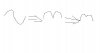
I noticed that when I measure the groung with an osciloscope, I do not have a flat line at this point.

is it normal? or I have problems with mi ground.

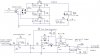
My voltage source is a +/- 12 volts the source of this DC voltage comes from a central tap trasformer 24V ac. The central tap is the ground, and here I connect all ground point of all my digital circuits and an analog signal that is acquired by a differential amplifier configuration.

Also I have noticed that when a relay is on my rectified signal that comes from the differential amplifier is noisy, it has disturbances.

Does I have to put a diode in serie from the regulator of 12V to the relay?


thanks
 
Please draw a sematic for better understanding.
Anyway, try connect the relay before the regulator, with appropriate serial resistor.
 
This is the diagram I did, that I would like to know if there some problems with the ground. In fact, the +12V (POINT:B) have some problems, when the relay is activated, also the POINT:A.

the DC level has ripples, (a small ac signal), I don't like it? when the Relay is on.

When the system starts I have a big DC signal at the output on POINT:A before some seconds it reach a stable level, according to the voltage generated by the current on the differential/current transformer.

If you have some commenst, all are welcome.
by the way, I put the ground of the oscilloscope at the ground point in the circuit.
Thanks in advanced
 

Attachments

  • half_ckt.jpg
    half_ckt.jpg
    79.2 KB · Views: 1,046
The pics don't show.
Just a question. Are you familiar with oscilloscopes? If not, the problem may be that the oscilloscope and the circuit does not share the same ground. In other words, the ground is floating.
The ground is used as a common reference for both the CRO and circuit. The CRO's ground is most of the time earthed foor safety reasons. The transformer is an isolating device. If your circuit is not earthed, it's ground will be floating.

Also, switching circuits, mostly digital circuits, can cause rippling in the supply rails. This rippling is normally reduced via coupling capacitors.
 
Well, I think I am not an expert using the oscilloscope, I just put the two point one to the common ground and the other to the voltage point, I don't have earth ground, Just the central tap is the common point to +/-12 volts and 5 volts.

what values does the coupling capacitors have to be? and where?
near to the relays (i am using two), and one near the microcontroller, and another near to the TL084 (opamp), if here is needed, two of them will be, isn't it? what values?

ceramic or electrolitic
 
sardineta said:
sardineta said:
This is the diagram I did, that I would like to know if there some problems with the ground. In fact, the +12V (POINT:B) have some problems, when the relay is activated, also the POINT:A.

the DC level has ripples, (a small ac signal), I don't like it? when the Relay is on.

You don't have much in the way of a reservoir capacitor on the output of the bridge rectifer, a 1000uF or so would be nice!. As it stands I would suspect you probably have a lot of ripple on the input to the regulators - you can check with the scope.

Your relay is marked as 5V 120 ohm, and connected to a 12V supply?, this isn't going to do the relay any good, and it will also overload the 100mA regulator which feeds it - 120 ohm at 12v equals 100mA, plus whatever the opamps take.

If your supplies are poor to start with, full of ripple, and unable to provide enough current - it's not suprising it doesn't work very well.
 
I see some problems:

1/ 24VAC rectified is dangerously close (34v) to the +35v rating of the 78L12 and over +30v for a 78L05
2/ You switching a 5v relay on a 12v line. The 120 Ohm resistance will draw 100mA from this regulator which is the max current spec for this with some heatsinking. See note 2 of National's datasheet.
3/ U1,2,3 are drawn with no GND connections.

Nigel and I must have responded to this at the same time :lol:
 
Thanks a lot!!!!

I have corrected the diagram, the relay is fed with 5 volts.

what you recommend me to do with the transformer, Does I have to change it by 12 volts AC
 
The relay seems to be running off the 5V rail. Anyway, as what Nigel has mentioned, you lack a large input reservoir. Also, try using 10uFs, if not 100uFs for your regulator output caps. Lastly, maybe this was left out in your schematics, you did ground your regulator COM pin right?
 
I made wome mistakes while wiring the circuits in circuitmaker

but in real life all are wired correctly.

in summary:
1: a 10,000 uF at the output of the full wave rectifier will be better instear of the 100uF

2: a 100uF (electrolitic) capacitor will be better instead of the 0.1uF ceramic capacitor

3.- the 120/24 transformer will be changed by another one of 120/12 volts,

The 120V is perfect no ripples, I have found in some litterature that a ceramic capacitor is conected in parallel between the two cables of the 120Vac, does this will prevent any outside noise?, what value will be perfect? do you recommend me to put it or not?

thank you!
 
It's stated in your schematics 120Vac. You sure no ripples? :shock:
Anyway, the diode bridge merely provides full-wave rectification. A large capacitor is required to smooth it out. See my pic. Apologies for the bad drawing :lol:
 

Attachments

  • argh.jpg
    argh.jpg
    8.2 KB · Views: 1,010
I went to buy some electrolitic capacitor, I will put right now a 470uF 100V capacitor, this is the largest with the small size. bigger capacitors are enourmous.

Does I have to change the 0.1uF cap by some of 100uF at the output of the regulators, too?

does I have to put a resistor in series between 5V and the relay?
 
I found ripples in the input of the 12V regulator, with a cap of 470uF at 100V it was better, however, at the input of the 5 volts regulator it is ok, no ripples with a electrolitic cap of 100uF at 50V.

As Nigel sais, I have to come back to the store to buy the 1000uF, I was confused and I asked a 10,000uF, I was amaized when I saw the big cap.

well, with the transformer 120/12Vac, I do not see more than 8 volts regulated so that why I choosed the 120/24Vac, the adviced TheOne let me know is true but I think it concerns when I do not take into account the central tap.

In this app. I am using the central tap so I see half the entire signal If I measure from the two extremes of the transformer.

If I am wrong, let me know
 
With the center tap 12+12VAC is perfect
 
Guidenve/review needed

I'm building prepaid energymeter with 8051 based 89c668 microcontroller.
ADC used: PCF8591
since ADC is unipolar, AC mains supply is rectified and given to ADC.

Mains supply >>> Potential/Current Transformer >>> Precision Rectifier
>>> ADC >>controller

For precision rectifier, I have used TL084 opamp.
I'm using +/- 12V supply for it from 7812/7912 .
For ADC, controller, LCD, keypad, etc.. power supply I am using 7805.

Will it be fine if i connect 7805 ahead of 7812 supply.
Transformer used is 18V center tapped, 1Amp.


Also i'm using Relay for disconnecting the load after balance is expired.
Will this affect power supply o/p. ?
How/Why relay would affect other ckt performance?

regards,
Shantanu.
 
Hi
I think it is possible with the 5 volts regultors, since the +12v regulator does not requiere too much current, however due to the current limiting I prefer to place all regulators at the same level, so I do not overcharge a regulator.

the relays have a spike when you turn them off, so it is necessary to place a diode, 1N914 or 1N4148 when your relay requires 15mA. the band must be with the possitive.

I haven't proven but I will use a TVS, transcient voltage suppressor, instead of a diode. Hope it will work better that the diode.

is there any other comments
 
sardineta said:
I haven't proven but I will use a TVS, transcient voltage suppressor, instead of a diode. Hope it will work better that the diode.

is there any other comments

I don't see the point in trying a TVS?, a simple diode does all that's required, a TVS isn't going to give any better protection, and may not give as much!.
 
Diode is must

Diode is for free-wheeling action and its must, i know that.


I would like to know if there some problems with the ground. In fact, the +12V (POINT:B) have some problems, when the relay is activated, also the POINT:A.

the DC level has ripples, (a small ac signal), I don't like it? when the Relay is on.

I'm asking abt this also.
 
Nigel
this is a good point, can you tell me where TVS's are convenient?
I am using an axial TVS. I guess they protect inputs and outputs pins from power noise or signal noise. There are others TVS in my circuit, one in the reset pin, another between Vdd and Vss and some others in some inputs pins where the circuit is closed by a push botton.

thanks in advanced
 
Status
Not open for further replies.

Latest threads

New Articles From Microcontroller Tips

Back
Top