Continue to Site

Welcome to our site!

Electro Tech is an online community (with over 170,000 members) who enjoy talking about and building electronic circuits, projects and gadgets. To participate you need to register. Registration is free. Click here to register now.

  • Welcome to our site! Electro Tech is an online community (with over 170,000 members) who enjoy talking about and building electronic circuits, projects and gadgets. To participate you need to register. Registration is free. Click here to register now.

grid tie help

Status
Not open for further replies.

takis365

New Member
hi
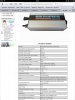
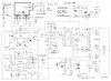
i have grid tie micro inverter 12v dc to 220v ac
this is have switching converter 12v dc to 350 dc and output h bridge mosfet.
have pwm sg3525 for dc converter and one controler for full power from solar panel.
on output gate mosfet driving from ac main grid 220v
the mosfet for ac is 13N60

have anyone circuit for this ???
thank you
sorry for my english
 
Last edited:
Hi.

Had a similar problem like thirteen years ago with another cheap DC/AC converter that failed. No schematic was to be found back then.

The best you can do is probably continue searcing the web for it, or you can ask the manufactor if they have a schematic and can sell you one (you'lll probably have to pay for it).
 
Thanks for the reply.
really is a cheap thing.
But I have great curiosity how does that called this technique ???
 
If you are wandering about what it takes to make a grid tie inverter I suggest you read through the collection of threads here related to grid tie inverter DIY designs.

Once you understand the tricks behind the switching circuits and how to time them to synchronize to the AC power lines it is really simple to do. ;)
 
ok
on high side of h bridge have one transistor and some resistors and capacitors for each gate mosfet (two mosfet and +350v dc)
on low side of h bridge have one diode for each gate mosfet only (two mosfet and -350v dc)
all these connect to ac power line
also on each mosfet between gate and source have one zener i don't know what is this
how i can find circuit or any link about this tricks
thank you and sorry for my english
 
Without a schematic it's nearly impossible to guess at how your output stage is designed.

Any way you could reverse engineer yours and draw one up for us?
 
Image0003.JPG
 
this is the schematic
I do not know what is the c22,c23,c24,c21.
also d11,d12,d13,d14 this is a zener but do not know how much is
Tests made ​​in luck capacitors ,work but not very well.
if someone knows let with help
 
I have been scratching my head on this circuit for two days now and from what I can see the high side switching is done with a combination of a sort of charge pump and for lack of a better term a polarity detector and minimum threshold voltage switching point limiter.

The bottom two switching devices appear to be getting turned on when ever the AC line polarity matches their gate inputs and the top two switching devices only get turned on if the polarity is correct and it is above a minimal voltage point determined by the zener diodes.

I am guessing this zener diode setup must be how they create the needed zero crossing dead band lower voltage limit referance points, where the polarity of the AC cycle reverses, to prevent over current damage to the switching devices once the line voltage drops too low on each half of the cycle.

Still guessing though.

What brand and model is this GTI? I am curious now.
 
Last edited:
This schematic have almost all the micro grid tie inverter mttp.
If you see the ebay has such.
There are from 250 watt up few kilowatts.
with SUITABLY mosfet low rds (I did test) works well.
As I wrote and above working with the main board.
when i get the voltage + 350v and - 350v from the main board and with this bridge it work well .
I did not put the zener (i do not know what is this).
Now i want to make test with solar panel 12volt and inverter pwm dc to ac (I will lift the ac +350 /-350 volt)
if you want tell me your opinion ????
I do not know if you understand me 100% because English is a problem for me.
thank you
 
Since you have shown us this much how about showing the whole schematic! :D

By the way the 340 volts is just 340 volts. there is no plus and minus referenced to a center 0 volts point.

In your GTI unit the minus is considered the common ground point for the 340 volt positive side.
 
Only lasted 2 days. Suncon WVD-260W-230V/50Hz/120V/60Hz Micro Grid Tie inverter

www.sunconpv.com

SC-1160-002 / WVD-260 / (230V/50Hz) 90usd/piece(FOB Shenzhen) for 180-350watt solar panel

bought one from china for 90US. Not much fun as it stopped working after 2 days using one 248Wp Bosch 31V/8A panel, and british sun.

Suspect, it can't handle power surges.

Will try to fix it when I find some time.

I like the idea of this circuit, though. Tcmtech, let's build a beefier one which lasts a bit longer than 2 days...
 

Attachments

  • image.jpg
    image.jpg
    546.8 KB · Views: 1,446
Last edited:
I like the idea of this circuit, though. Tcmtech, let's build a beefier one which lasts a bit longer than 2 days..

Sure. Take a number. Yours is #927 and I am presently serving #8 so it might be awhile before I get to you. :p
 
Status
Not open for further replies.

Latest threads

New Articles From Microcontroller Tips

Back
Top