Continue to Site

Welcome to our site!

Electro Tech is an online community (with over 170,000 members) who enjoy talking about and building electronic circuits, projects and gadgets. To participate you need to register. Registration is free. Click here to register now.

  • Welcome to our site! Electro Tech is an online community (with over 170,000 members) who enjoy talking about and building electronic circuits, projects and gadgets. To participate you need to register. Registration is free. Click here to register now.

Greenhouse door opening system

Status
Not open for further replies.

daniel.canea

New Member
Hi all,sorry if I post in the wrong section,It`s my first time!
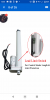
I am trying to create a greenhouse door opening system,using an 12VDC temperature controller thermocouple,and an 10 inch 12VDC linear actuator.
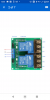
As far as I know,I will have to reverse the polarity to be able to retract the actuator,and this is where I don`t know how to do it.
I will atach the schematics of the thermocouple,maybe youguys can shed some light here!
Thanks!

itc1000f.jpg
 
10 inch 12VDC linear actuator
I have two types. One type I need to remove the power when the actuator hits the end. The other type has a switch on each end to stop the motor and cut the power.
Some actuators have 2 wires, or 3 wires or 4 wires.
I have a window where power opens and hold open the window but removing the power and a spring returns the window to closed.
We need to know more about your actuator!

The actuator is a 2 wire,with end switches,from Ebay!
 
So a two wire, you must have to reverse the voltage to reverse the direction. OK. I need to think.

12V powers the 1000F. The cooling switch (7-8) sends power to a relay. (DPDT type). The relay sends power to the actuator. When "cooling" is open no power goes to the relay coil but when "cooling" closes the relay coil gets power and switches the relay. The relay reverses the voltage on the actuator.
118405
 
A picture from google that does the same thing. (different wiring but the same effect)
118406

118407
 
I'm surprised at you guys. it's just a modification of the "chicken coop door" problem. or "door lock actuators".

the "door lock actuator" wiring does provide dynamic braking, so no overuns. You can start with two DPDT Automotive relays. You can buy a dual relay harness that has some of the interwiring of the relays done for you.

It start's here: **broken link removed**

The relay terminals should face down. Grrenhouse: automotive relays, I think is better choice.

In any event, the common terminals of both relays go to the motor and the NC terminals of both relays go to ground. The NO terminals goto +12.

You activate one relay for up and the other for down. If they are both off, then the motor also brakes.

You can use cool to activate one relay (open the door) and the other heat (close the door). That, I think makes sense.

You may want diodes across the relay coil reverse, e.g. 1n4002. This protects other electronics when the relays switch off.

If this is a battery application, you may wish to install your own limit switches. To install your own limit switches, the contact rating of the limit switches must handle the automotive relay coil current which is about 150 mA give or take.

To add an up limit switch, just put it in series with the up command relay. When the door reaches the UP limit, the switch opens. Vice versa for down.
These relays would then not be activated when the door is at a limit, saving power.

I mixed up up/down and cool/heat or open/closed. Take your pick.
 
I'll respond. No mention of a heater in the first post.
Yep, good to have many ways of doing things.
We don;t know how this system is powered.
Line or battery or backed up battery or some other way?
Well you could use Heat to run a heater, just use a DPDT relay there.
The TS could have condensation problems with the controller and could with the relays too.
Automotive relays are, I think, better designed for the environment.
He didn't ask about enclosures, but it needs to be considered too.
I THINK that the internal actuators limit switches are probably designed more for actuator protection and I think overrun is possible.
HEAT and COOL does allow fro a differential temperature.
Is there a possibility for the door to "hunt" or constantly open/close around the setpoint? Using heat/cool would eliminate that.
e.g. heat >78, cool <75 Controller should have hysteresis.
It was daunting for me back in the 80's to have "discovered" DIN rail
I keep envisioning this "drop out" relay design that was wired with all yellow wirew.
It would drop out a 240 VAC heater and close a valve
"They", some one at work also used ground for Neutral for a source 120 VAC.
Your definitely correct, the heat relay could be for supplimental heat heat which might be activated a much lower temperature.
For the TS, there is a lot of stuff that comes from experience.
In what I did for work related projects is I made my stuff more line "appliances" that could be re-used. Some designs lasted my entire 30 year tenure there.
 
Well you could use Heat to run a heater, just use a DPDT relay there.
This is not my project. But, I may have to use heat at night and cool in the daytime so a switch is not good. The last several nights we had snow and freezing temperatures. Tomorrow it will be 75F and so much sun that I will have problems.
Is there a possibility for the door to "hunt"
My controller has 5 degrees of temperature between on and off to stop that.

I have "heat" set just above freezing. Cool-1 to open the windows and doors for 'free cooling'. Then Cool-2 to turn on the fans. I live at high altitude where the temp changes too much from day to night. We have months of freezing at nights and turn on the fans in the afternoon.

My controllers have room inside the water proof box. I open up the box and add relays.

I like our point about the environment. I have seen water + chemicals eat up solder joints and wires.
 
I'll respond. No mention of a heater in the first post.
Yep, good to have many ways of doing things.
We don;t know how this system is powered.
Line or battery or backed up battery or some other way?
Well you could use Heat to run a heater, just use a DPDT relay there.
The TS could have condensation problems with the controller and could with the relays too.
Automotive relays are, I think, better designed for the environment.
He didn't ask about enclosures, but it needs to be considered too.
I THINK that the internal actuators limit switches are probably designed more for actuator protection and I think overrun is possible.
HEAT and COOL does allow fro a differential temperature.
Is there a possibility for the door to "hunt" or constantly open/close around the setpoint? Using heat/cool would eliminate that.
e.g. heat >78, cool <75 Controller should have hysteresis.
It was daunting for me back in the 80's to have "discovered" DIN rail
I keep envisioning this "drop out" relay design that was wired with all yellow wirew.
It would drop out a 240 VAC heater and close a valve
"They", some one at work also used ground for Neutral for a source 120 VAC.
Your definitely correct, the heat relay could be for supplimental heat heat which might be activated a much lower temperature.
For the TS, there is a lot of stuff that comes from experience.
In what I did for work related projects is I made my stuff more line "appliances" that could be re-used. Some designs lasted my entire 30 year tenure there.

This is what I am planning to use,the whole setup will be powered by an 12VDC 10A power suply,no battery yet.
 

Attachments

  • Screenshot_20190524-135555.png
    Screenshot_20190524-135555.png
    469.6 KB · Views: 158
  • Screenshot_20190524-135521.png
    Screenshot_20190524-135521.png
    833.2 KB · Views: 166
  • Screenshot_20190524-135450.png
    Screenshot_20190524-135450.png
    591.7 KB · Views: 160
Status
Not open for further replies.

Latest threads

New Articles From Microcontroller Tips

Back
Top