Continue to Site

Welcome to our site!

Electro Tech is an online community (with over 170,000 members) who enjoy talking about and building electronic circuits, projects and gadgets. To participate you need to register. Registration is free. Click here to register now.

  • Welcome to our site! Electro Tech is an online community (with over 170,000 members) who enjoy talking about and building electronic circuits, projects and gadgets. To participate you need to register. Registration is free. Click here to register now.

Google translate suggest "device sheet" or "apparatus sheet" but that cannot be ?

Status
Not open for further replies.

Grossel

Well-Known Member
Hi.

I'm just creating another boring thread because I cannot find the correct terminology for a particular thing.

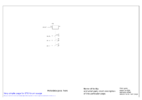
This time, I'm referring to a paper, a page or set of pages as a sub part of electrical drawings (this is probably more geared towards wiring diagrams in automation facilities). Very simple example - A paper containing one or several relays being in use. The paper describes the component designation, available terminals and their functions and then a reference or page number for each terminal being used in order to be found in the drawing.

This is only useful when having facilities with large number of pages, you know the component designation and want to look it up in the electrical drawings.

Why do I suspect Google throwing off a bad translation? Because on an image search, I find a whole lot of drawings, but none that fill the function I described, most of the drawings are not related to electrical either.
 
Hola Grossel

Are you aware of a better translation that could be suggested?
You could do any time you want.

About ten years ago, "cuñado" (Spanish) had no proper translation to English. Somebody told Google the right one.
Brother in law, BTW.
 
Grossel

I think you are looking for something which tells that RL4 is at grid F6 on sheet 5.
Yes?

I don't think that there is a formal expression for such a thing.
Maybe:

Device Location Key
or
Device Locator Key
or simply
Location Key

What do you think?

JimB
 
Continuing....

Looking at a few equipment handbooks,
Hewlett Packard offers "Assembly and Component Locations"
and
Tektronix offers "Device Location Table"


JimB
 
Schematic drawing or schematic diagram. This description applies to circuits as well as assemblies of relays and other components that are part of an industrial control system. In a complex system, that can cover many sheets, each sheet may have alphanumeric grid locators printed around the border.
 
Are you aware of a better translation that could be suggested?
No, of course no - otherwise I wouldn't have posted here in the first place.

I think you are looking for something which tells that RL4 is at grid F6 on sheet 5.
Yes?
Yes, exactly. And a typical paper also have a simple drawing of the component where one can see what terminals is available.


Device Location Key
or
Device Locator Key
or simply
Location Key

What do you think?
My English isn't at the level that I can hear/taste on a word and come up with a clear opinion on what fit best.

But I think this "locator key" is the same, because some manufacturers have just a table like this in the beginning of the document sets, and then it is like a table of contents, but also list each components manufacturer, component name and also rudimentary specs (i.e. voltage levels on coil).

The papers I ask for do include a simplified drawing of a component is shown, it may be inputs and outputs, along with a tag that specify location for a terminal or group of terminals.
 
Very simple example - A paper containing one or several relays being in use. The paper describes the component designation, available terminals and their functions and then a reference or page number for each terminal being used in order to be found in the drawing.
The nearest formal name I know of is a "Reference designator"?

Or just index or cross-reference?
But many manufacturers use their own systems.

Some manuals have a component identification section, with outline data on every part used - but few now, it's pretty much gone out of fashion.

Or, some have coordinates, eg. along the top and side of each page, and each sub-component has the page and grid location of the main part.

Some schematics prefix such as relay contacts with either the the page number that the coil and contact arrangement details are on, with the coil having the contact diagram below and all used contacts identified with the wire number, column number or the page / grid location the contact is used, as in the image below.

Some also have mechanical schematics of the control panels/cabinets, with all parts shown in their relative positions, IDs to match the ones in the electrical schematic and with all terminals identified with the wire numbers that connect to them.

There is no single standard, unfortunately.

Schematic.JPG
 
I'd drawed up a very simple example on how such a page can look like. rjenkinsgb are probably correct in that there are no standard - the example I draw up is based on how some manufacturers set up a schematic paper.
 

Attachments

  • page with reference designator.png
    page with reference designator.png
    81.7 KB · Views: 206
When I had a SCADA system in the late 70's with 2 umbilicals to a rocket launch and 100 analog relay channels and 100 power relays in a box from 15 to 25A to power experiments and charge batteries, I used a wiring list for the functional to the physical in a table for the cable assignments external and internally a component pin to connector pin with a K# reference designation "REFDES" without a functional name as it could be anything.

You may have your own hierarchical logical "refdes" for cables, boards and components each with description options . I recall PADS and other tools were good for hierarchical schematic dwgs that could be used as well , starting with the block diagram.
 
For elevators there is also something called the 1 Line Diagram
1659462358862.png
 
After some thinking and reading, I realize you're probably right in there is no standard term for this.

At my work, I've seen 2 manufacturers that have this section of "device sheet" (bad translation) and many others just doesn't care section them out and just go for "wire diagram".
 
Status
Not open for further replies.

Latest threads

New Articles From Microcontroller Tips

Back
Top