Continue to Site

Welcome to our site!

Electro Tech is an online community (with over 170,000 members) who enjoy talking about and building electronic circuits, projects and gadgets. To participate you need to register. Registration is free. Click here to register now.

  • Welcome to our site! Electro Tech is an online community (with over 170,000 members) who enjoy talking about and building electronic circuits, projects and gadgets. To participate you need to register. Registration is free. Click here to register now.

Getting your child interested in electronics.

Status
Not open for further replies.

ke5frf

New Member
Hi there fellows and ladies.

My son just recently turned 9 years old and this year, instead of the usual video game, skateboard, DVDs, or board game useless junk that he quickly bores with I got him some electronics projects.

**broken link removed**

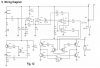
I got him this simple robot kit which uses IR diodes to drive a BJT H-bridge through a comparitor configured op-amp. Simple circuit and even I enjoyed helping him build the bot....(Though I got the connector for the battery pack backwards on the first go, which had interesting results because the circuit tapped 4.5 and 6 volts from a 4-battery (1.5v each) configuration. One motor ran no matter which way the power switch was set and the other didn't run at all!!! LOL, took me a few minutes to think it through.)

He learned a few new words, though he didn't quite get them (transmister, compaticer, dye-o...very cute)

**broken link removed**

I also got him one of those 300-in-1 electronics lab kits. We built the first project, the chirping bird which is a simple audio oscillator whose frequency is determined by the light sensor. I can't remember just now if its a resistor or diode used as the sensor. I'm not at home to look.
We also built the AM crystal radio with the germanium rectifier, but no luck finding a suitable earth ground for the antenna so he wasn't impressed!!!

Anyway, it was difficult keeping him attentive and truly interested. My son is VERY sharp, a quick learner. But I wonder if this is still a bit over his head. He gets impatient and only seems interested in the "finished product" and not the pieces that make up the whole and how they all work.

My goal here is not so much to inspire a future design engineer as much as fostering analytical thinking abilities, an interest in science in general, and practical skills that will help him with any career.

I confess my own father never spent much time doing that kind of thing. He did teach me to use a lawn mower if that counts ;)

Am I going about this the wrong way? Can anyone share their experiences with their children???

If I could get him interested and spark a desire, I think I could pass my knowledge along and give him a superior head-start toward an engineering career.
 
Last edited:
I had the 300-in-one kit when I was a child. Only back then, it was 150-in-one. Man, I loved that kit. I would use it for hours opon hours. Nowawdays, with micorcontroller kits, there isn't nearly as much interest in learning electronics. Personally, the electronics I learned building the projects in the kits is an advantege to me in my (former) job as an IC designer.
 
I'm going to be having the same problem. It's hard to get him interested in blinking lights and little beeps when every toy he's ever had does it, and even cheap crap toys you get from McDonalds do it. Then more complex projects are too over his head. It's hard to get interested in the basics now-a-days when electronics that does this simple stuff is so ubiquitous and mundane.
 
I had the 300-in-one kit when I was a child. Only back then, it was 150-in-one. Man, I loved that kit. I would use it for hours opon hours. Nowawdays, with micorcontroller kits, there isn't nearly as much interest in learning electronics. Personally, the electronics I learned building the projects in the kits is an advantege to me in my (former) job as an IC designer.

Yeah, to be honest with you I think I got the kit as much for myself as for him!!! I wanted the experience of watching him learn some things while getting the opportunity to build some circuits I've never built, only studied.

I have had formal training in my career, but not so in depth as a 4-year degree would provide, and much of my knowledge is self-taught through books, internet, and practical experience as a troubleshooter. Actually toying with such circuits will be educational for me as well.
 
But that's a good thing. Children love to emulate thier parents. That's how you're going to get him interested, even in just blinking lights.

My favorite project was the sirene. I spent hours changing circuit values and observing the changes in sirene tone, etc.
 
I'm going to be having the same problem. It's hard to get him interested in blinking lights and little beeps when every toy he's ever had does it, and even cheap crap toys you get from McDonalds do it. Then more complex projects are too over his head. It's hard to get interested in the basics now-a-days when electronics that does this simple stuff is so ubiquitous and mundane.


Absolutely! Everything is a "black box" to people nowadays, and worse...very few people even CARE to know how things work...at all. Our society is so integrated with electronic devices at every turn, yet people just shrug and don't care to know the basic theory that makes things work!

As cheap and disposable as things are, I understand in some ways...but I take note that SOMEBODY has to understand this stuff in order for newer, smaller, improved electronics to develop. And it stands to reason that the person with that knowledge has career opportunities that others don't.

Unfortunately though, it seems in American manufacturing that this stuff is being outsourced more and more.

Is it even worthwhile to encourage this, given that jobs are going overseas?

I'm thinking that the underlying analytical skills are the real goal, and genuine interest in electronics is good but not as important.

I guess I have a hard time with just accepting that things work without having any idea how. People are afraid to fix a coffeepot nowadays, let alone a high end product.
 
I think all you can do is your very best to expose your children to many things and encourage exploration and experimentation. While I think you can have a profound impact on your children I don't think there is an exact formula or procedure to get them to do the things you want them to do.

As suggested you can lead by example but if their interests lie elsewhere then you may have to accept that. To do otherwise might prove stressful to you and the children.

In my own case, my son was interested in audio equipment (car stereos to be specific) so for a time we approached electronics from that direction. He remains interested but as adult he's really not inclined to do as I might do with the hobby.
 
Here's what I did for my boys (ages 9,11,13). I got them a small breadboard and some jumper wires, leds, diodes, resistors etc. We've salvaged a couple of small DC motors off of old cdroms and they build little lego structures around it. Wire up a switch and they have a ball. We made some kind of crude catapult with a large printer motor.

Only one of them seems interested in learning more, so I showed him basic 555 timers and how the R/C effects delay.

It all started with the breadboard though.
 
I got my nieces (ages 11 and 13) somewhat interested in electronics by making a switch for an air-powered rocket launcher (**broken link removed**). Having a fun goal like shooting off rockets helps.
 
I can find out what it was called if you want, but my neighbors got this kit that was like lego electronics. The components were built into these small clear plastic pieces and they used buttons (yes like clothing buttons) as connectors. It came with a project book, but more importantly it came with things like LED's motor's a solar cell, speaker oscillator and things like that. The circuits were idiot proofed so aside from dead shorting the battery source there was little you could do to hurt anything. I thought it was very cool, perfect for a 9 year old.
 
Robotics would be a good field to catch his interest, he can branch out in several related fields, and there a lot of different areas to explore. Its a field that will continue to grow and mature with him. Microcontrollers and programming are other good choices, since he can make things uniquely his. Unfortunately, most of the fun beginner stuff, has been turned commercial, so there isn't much fun left.
 
Just make sure you aren't pushing him into this path. When I was younger my dad got me this build-it-yourself electric motor kit that could be used on a little plastic boat. I wanted nothing to do with that and it just made electronics unattractive to me. However, when I started showing interest in computers he bought me all the parts required to build it and I built it with a colleague of his who showed me how to do it. Furthermore, when I started showing interest in electronics he bought me a simple AM radio kit that I built. Only when I took the initiative to show interest in it, did it become valuable to receive that push. Although I'm now a Computer Engineering student, I still think that receiving a lot of electronics kits before I was ready would really push me away from going into this field. It's really necessary that you let him know that this is his choice to make, not yours.
 
Last edited:
Lady Bug robot kit

first of all, congratulations. i find it amazing that your nine-year-old has been able to understand any aspect of the ladybug robot kit, even if he has trouble with some of the pronunciation.
unfortunately for me, however, i am not at all gifted with electronics. i am in year 12 and have recently made the same ladybug robot and am required to explain exactly how it works. i understand most of the components individually, but it would be great if someone could give me a step-by-step based on the attached circuit diagram.
my robot doesn't work by the way - only the right-hand motor turns :S this isn't overly important, however, as long as i can explain what went wrong!
i really want to stay top of my physics class because we have less than a month left of school and this is what it all comes down to... please help!!
bridget
 
forgot to attach the diagram... here it is

oops! hopefully it's attached...
 

Attachments

  • ladybugDiagram.jpg
    ladybugDiagram.jpg
    40.9 KB · Views: 405
This is what I think it is.

The Q7 and Q8 and the cirucitry around it form a flashing circuit.

How it works:

When voltage is applied a RC timing circuit is set up using R17, R15, C2, R14.

Electron current flows from ground through these components and builds up a neg. voltage at the base of Q7 (NPN) causing Q7 to shut down, for a time denoted by the timing circuit.

That's why R14 is so large to allow a C2 current to build up quickly at the base of Q7. If this resistor was to small then the Q7 would conduct quicker not allowing the capacitor (C2) to fully charge into it's base.

The reasom for that is because now Q8 would be conducting, so current through C2 could be next to nothing, which in turn would stop the flashing process from happening.
Thereby the LED would be dimly on, or fully on depending how much Q8 is conducting.

Another reason for R14 so large is there is no base to ground resistor voltage divider to put at the base, the base is effectively floating.

When the C2 begins to charge to the point where less current flows through it, then the base of Q7, will begin to raise positive, thereby conducting and sending a neg. going signal into the base of Q8, (PNP) which will turn on this transistor causing it to allow current to be dumped quickly through the LED through Q8, the LED flahes on,

But now C2 is being discharged, to the point where current can begin to flow through the RC timing circuiot again shutting down Q7 which in turn shuts down Q8. Now the LED is off again until C2 is charged to the value it was before, starting the whole process over continuously.

If C2 were connected to ground, then there would be no way to discharge the capacitor, but by placing it at the junction of R17 and the LED load then it has a way to discharge for another cycle to begin.

EC2 and R13 is used as a supply decoupling, network, this keeps the oscilator from feeding oscilating currents back into the battery. That's why R13 is so low so as to not have a great effect on the voltage at the base or emitter of Q7 and Q8, but just enough influence to keep isolation between this circuit structure and the rest of the circuitry, which all use the same common battery source.

R17 is mostly low so to be used as a current limiting resistor for the LED.

The LED itself is an IR, so this is probably being used for obsticle avoidance. (I'm just guessing NOW)

R16 is used as a coupling resistor from the Q7 collector to the base of Q8.

Electronic analysis:

Looking at the network (EC2 - R13) this forms a lowpass filter, so any high frequencies from the oscilator circuit will pass through EC2 to ground, thereby keeping the supply free of parasitic oscilations. The cutoff frequency for this network is in the range of 16 HZ. (where F = 1 / 2*pi*R*C)

Now when power is applied to this oscilator, there is a RC time constant also with this network.
Tc = R * C ( where R is in Megohms, and C is in microfarads.)
Tc = 10ms. This is where the EC2 has charged up to 63% of supply voltage.
So in 10ms. the voltage across the EC2 should have reached around 3.78v. which leaves around 2.22v. across the R13. After 5 Tc. the capacitor is considered theoretically fully charged so in 50ms. this network should have close to 6v. dropped across the EC2.

Now positive supply is fed into the oscilator nertwork the base of Q7 and the emitter of Q8.
Since the circuit is powering up there is another Rc network consisting of R13, R14, R15, C2, R17.
After googling Disc capacitor values, found that 104 for C2 would be 0.1uF.

Initial current through this network will be around 3.32uA.
So the voltage drops would be
R17=50uV.
C2=0V.
R15=15.5mV.
R14=5.976V.
R13=332uV.

Therefor the voltage at the base of Q7 ( VBQ7) = 15.65mV.
That would keep Q7 OUT of conduction. Because Vbe of Q7 is around 0.6 to 0.7 V.

Now
When time is greater than zero

A time constant is set up which, This Tc = 180ms. so after 180ms. the voltage across C2 should be around 3.78v.
and now a current flow of approximately 1.23uA.

Voltage drops would be
R17=18.45uV.
C2=3.78V.
R15=5.78mV.
R14=2.214V.
R13=123uV.

So now that puts around 3.78V. at the base of Q7, thereby Q7 is now able to conducting because the base voltage needs to be around 0.7v. to conduct and it is well within that region.

NOW without getting into Transient analysis, it looks like it will take shorter than 1 Tc. for Q7 to begin to conduct. So the frequency is higher than 5.5 Hz. using the 180ms. calculation. (1 Tc)

Just interpolating this, assuming before 1 Tc. the capacitor charges in a linear manner, just for rough calculations, than it would take 30ms. for a VB Q7 to be around 630mV.
So 1/6 of 1 Tc would cause Q7 to start conducting.

This freqency could be around 33 Hz. This is Not using transient analysis, but assuming that before 1 time constant, that the voltage across C2 is very close to linear.

So this rough estimate of freq. for the oscilator is a high enough freq. to be filtered through the EC2 R13 low pass filter, which has a cutoff at around 16 Hz. As stated up above.


===================================================

Q1 - Q6 and its circuitry form a motor driving H-Bridge.

How it works:

First motor M1 is continually running, (and running forward) because its connected directly across the supply. I don't know why, but that's what the schem. shows.

Q1 and Q2 are the Base drives to turn on the proper combination of transistor Q3 -Q6, which gives the forward and reverse drive of the motor. (M2).

A positive sig. into Q1 will drive a pos. sig. into Q5. Q5 will drive neg. current through M2 neg. term. and current (electron) will flow the path through M2 and the collector emitter of Q3, to supply voltage.

Now at this point M2 is forward running.

Now if a signal on Q1 is off and a sig. (pos) comes to Q2, then the emitter of Q2 will drive pos. voltage into the base of Q4, so now Q4 turns on and drives electron current through the pos. term. of M2 making it run in reverse, and the electron current continues the path through Q6 collector , emitter, to the supply.

That's an overview.

Electonic component detail:

Pos. voltage signal to the base of Q1,would need to be greater than around 1.4v. Because it's base is 1.4v. above ground. Now its collector would be around 3.8v. above ground due to the Vbe of Q3. So a signal into Q1 base will cause Q1 to conduct, the Base current from Q5 will now be Q1's emitter current, this current will flow into the base of the PNP Q3 causing it to conduct.

So now with Q5, conducting and Q3 conducting there is a completed path for electron current to flow through the motor.


That's about it.

THIS IS MY TAKE ON THIS.

If I'm wrong someone will correct it.
 
Last edited:
I don't know about all the details, but you have a lot of it right.

A more general analysis and explanation:

The lower left side of the circuit is the amplifier and oscillator for the IR LED. I havn't bothered to work out the frequency.

The upper left side is the RX light sensitive diode with a sensitivity adjustment at VR1.

The next stage to the right is the two stage operational amplifier which amplifes the sensor signal and biases it for the next stage. D1 rectifies the signal for the comparitor circuit.

After D1, the sensor signal is fed to a comparitor which sets against a reference voltage, the threshold of which tells the robot it has encountered an obstacle. This is the logic/decision making part of the circuit.

The output of the comparitors drives one set of the robots legs via the H-bridge at the lower right (6 transistors)

The other motor is constantly driven forward.

One comparitor goes high, the other low, sets the motor driven forward by applying the voltage in one direction. This would be when the detector is not sensing an obstacle.

When an obstacle is encountered, the comparitors both change states, applying a reverse voltage to the motor and one side of the robot starts backing up, while the other motor remains forward driving (as it always does). As you can imagine, this causes the robot to turn as it backs up.

When the obstacle is cleared, the comparitor returns to its normal state, and both motors go back to forward movement, until another obstacle is encountered and the cycle repeats.

The other
 
hi all
i think electrontics is much practice with bit patient, but the harderst part is being patient when things go wrong. and i don't think analysing electronic circuit with analysing techniques like nodal, mesh inappropriate with 9 year old kid, just give some inspiring experience, the best thing is you do experiment with you kid. kids in that age is more sensitive to what there parent do, so if you show your are also very interest in electronics, kid might be catch that. and it is very common fade up about not working project, gave him time and start it in fresh breath with him. and don't show you giveup when the thigns go wrong.( i think this is the thing what my father do even though he is not much technical- he is a high school teacher, but things inspire me so much, i'm doning master degree in electronic, my father past away few year ago:( but i think he may very happy about me doing electronics and i am very very greatfull to my father because he is my very first teacher in electronics,)
goood luck
 
Thankyou so much!
Your explanation has helped impove my understanding to no end, I can finally get on with my last ever physics assignment and I'm thinking now I might just ace it XD
Thanks again!
 
in my childhood i was not that exposed to electronic based toys, but my dad used to provide me toyes and it lasts only one day on my hand, then it goes into pieces, the good way he used to encourage me is not to blame me for that, and adwised me to fix it as i know...though its mostly mechanical stuffs.

i dont think electronic basics are much important to motivate towords it, just let his mind work and do his things in any but in creative manner..help him n guide him, give him some questins of which answers can lead him to effort and solve it.

when his brain starts to work more technically then some day if it is his interst to go in electronics he would chose, if not in other field.

though i couldnt experiment on my child hood in electronics, after my 14 yrs, my interest went on electronics and i could better do all before i get my degree,

some one may have other ideas how to direct them or motivate them towrds..
 
My dad got me that exact 300-in-1 kit a few years ago as a gift (I was nine then too). That was before I seriously got into electronics, though.

We tried to build that AM radio, but also had trouble with the ground. That made me lose interest in it to.

I was the exact same way as your son. The stuff about resistors, capacitors, diodes, etc. want over my head as well, and I also felt annoyed by the little wires I had to plug in to the holes. To be honest, I was only interested in the finished product as well.

I still had fun with it though, and may not have even known what a resistor is without having had that toy. :)
 
Status
Not open for further replies.

Latest threads

New Articles From Microcontroller Tips

Back
Top