Continue to Site

Welcome to our site!

Electro Tech is an online community (with over 170,000 members) who enjoy talking about and building electronic circuits, projects and gadgets. To participate you need to register. Registration is free. Click here to register now.

  • Welcome to our site! Electro Tech is an online community (with over 170,000 members) who enjoy talking about and building electronic circuits, projects and gadgets. To participate you need to register. Registration is free. Click here to register now.

Getting input from a large array of sensors

Status
Not open for further replies.

Snowman

New Member
Hi,

I need advice on a circuit:

1) Description of current setup:

* I have simple light detectors using some passive components and photodiodes whose output is fed into 7414s to clean the signal up. The result is a TTL level 1 or 0 in response to dark and light conditions on the sensor, respectively.

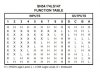
* I have 3 x 7-segment LED displays that are driven by chained
7490s and decoders - 7448s. All that is required to set the number is a serial set of pulses into the clock input of the first 7490 in the chain. This is NOT a rigid requirement of my circuit - just the way things are set up right now.

2) Problems and required advice:

* I would like to be able to count and display the number of darkend sensors - real time - on the LED display
* There are 150 sensors
* Sensors are spread out over a 1 meter (3.3ft) long surface

*I am concerned with form-factor of the final circuit for so many sensors
and realise that there are CPLD or PIC solutions that could accomodate this problem with more ease. But at this stage, I would like to implement the circuit with "off-the-shelf" TTL and passive components.

Thank you for any help in advance!

**PLEASE USE THIS EMAIL ADDRESS INSTEAD:**

ynospamavitalp@rogers.com
(remove the letter that sounds like "wye" and the words "nospam" to
get actual email)

Avital
 
I have a couple of harebrained ideas for you to kick around:

1. Load the outputs from your 7414s into a parallel to serial converter made up of nineteen 8 bit p-s converters (74164, 165, or 166). The serial output becomes the clock for your 7490s. You will need a clock (which you apparently already have), counter and decoder to generate load and shift commands. I'll bet this scheme is what you are looking for an alternative to.

2. Sum all the 74HC14 or 74HCT14 (you'll need CMOS for this) outputs through 0.5% (or better) 100k resistors into an 8 bit A/D converter. You'll need an 8 bit binary to BCD converter on the output, which I don't think is trivial. All the solutions I've seen require some sort of programming, be it EPROM, gate array, or microcontroller.
 
You would win that bet

Yes, absolutely correct! I am currently testing out ideas with only 8 sensors, I had a 74194(universal shift reg) laying around, so I figured I'd do the p-s conversion that way and use that as the clock. But, as you guessed, 19 chips only for the registers is something I'd rather avoid. I was hoping for a clever addressing scheme perhaps.

I totally agree on the ADC option - not trivial and probably error prone in the env. I described. I'm slowly resolving to the fact there may be no elegant TTL based solution. What would be your recommendations in such a case?

Thank you for your speedy reply :)
Avital
 
Well, I have to admit I haven't done a lot of digital design lately, so I don't know what's available. Here's a thought: I f you could find an 8 wide or 16 wide, tristate Schmitt bus driver, :roll: you could put them in an array (say 10x15 or 20x8) with all the outputs common, and set up x-y strobes. The output would be a little slow because of the high output capacitance. You would use the output to clock your counters.
I found 74HC7245 in a 1996 Philips databook. It's an octal Schmitt-trigger transceiver with tristate outputs - overkill, but... .
You could also use multiplexers. You can buy 16x1 analog muxes. I'm not sure about digital.
Regarding programmable solutions - I have no experience, but multiplexers and a Pic is the first thing that comes to mind.
 
Anyway you look at it, it would require a substantial number of chips to implement if you do not to use CPLD's or uC's. Here is another proposal:

Use a 150 count counter (clock, counter, and 150 outputs such as 15 x 4017). each output feeds an OC two-input AND gate, the other output of each AND gate is tied to each of your ON/OFF sensor signal. Tie all outputs together (with pull up resistor). This output will now become a clock to feed into your counter/display. Any sensor that is high when scanned will let the clock signal through, and be counted.

Jem
 
Seems like there's no novel solution

Ron,

I've tried playing around with the XY grid idea, I've interpreted it to mean:
* Setup sensors in an XY grid, say 10x15 (rowxcol)
* Each row and column is one data bus which is shared by all sensors on it
* At "end" of each bus, you put the Schmitt bus driver, then strobe them sequentially using decoders
* Sequential/combinational output from each xy strobe is ANDed to receive 1 or 0
* This output serves as a clock for the counter in conjunction with some sort of display resetting mechanism

(This also seems related/similiar to jem's idea)

Although this is probably the best solution so far (measured in min amount of components), under this-and some variant-interpretations, I'm still dealing with a large chip count - this will only become worse as I add more sensors.

Not to mention that I'm afraid of other noise issues between the sensors and circuitry - not that any design is totally immune - I'd still rather not have a design that is explicitly sensitive to them (TTL or CMOS). I've examined about 4 unique solutions now and I'm almost fully resolved to the fact that there simply isn't a clean way to handle so many inputs.

So, I now turn to CPLD's, which seem to be ideal for this purpose. What would any of you recommend in terms of a CPLD-development beginner kit? I've some clue as to what's going on with Xilinx solutions but would still appreciate some pointers. Should I just buy a CPLD that seems to fit my pin/macrocell count requirements, the demo board and a VHDL book? :)

Thank you guys for ideas and help!
 
Hi Snowman,

ive been looking at various matrix-ing arrangements for
this, but there is one requirement that you wanted,
which makes it a bit cumbersome.

exactly what do you mean by:
* I would like to be able to count and display the
number of darkend sensors - real time - on the LED
display


In particular what do you mean when you say:
'' - real time - ''


This is a real difficulty, and makes the arrangement
very awkward to accommodate.

And what on earth is a 'form factor', is that some
kind of wiring loom ? You're worried about the form
factor with so many sensors ?

This kind of setup puts me in mind of a priority
encoder, where progressive inputs become logical one
inclusively, and the output changes in real time.

I feel sure standard TTL chips could do this, but first
what do you mean by real time ?

John :)
 
Sorry for confusion

John,

Was afraid those words might cause confusion. I don't mean anything special by "real time"; I don't mean to imply time-critical application here or anything of that sort. I only meant to say that I would like the count display to be updated nicely - no flickering, not slowly, not too quickly, etc.

As for "form factor":
https://www.hyperdictionary.com/computing/form+factor
https://whatis.techtarget.com/definition/0,,sid9_gci212142,00.html

That is, with all the designs that have been discussed, the ttl (or cmos) chip count is quite high (>20 chips), this is what has prompted me to voice concern over that issue in the first place.

As for the arrangement you had in mind with the priority encoder, could you elaborate?

Thank you,
Avital
 
Hi Snowman,

Thank you for the links about form factor.
Its not a term i am familiar with.

The input pattern on a priority encoder gives a sort of 'ramp'
or 'slope' similar to the way you describe the light falling
on the array of sensors.

The table attached shows nine inputs, position ten or zero is
when all inputs are high.
The inputs are held high by pull-up resistors,
and active low takes them down.

The interesting thing is that the inputs are 'prioritised'
thats what the 'X' is for, the inputs of lower priority are
ignored.

If you aren't used to looking at these tables,
then just look at the middle row,
the row where 5 is marked as a low.

It gives the binary output for 5 thats fine.

What you can also see is that inputs 1,2,3 & 4 can also be low.
Cos they're marked with 'X's

Thats what i mean about the similarity to the row of sensors
you described, with light falling on a portion of them.
I was looking into an arrangement using this kind of thing.

I'm still thinking about this,
Would it be a problem to have two rows of sensors
instead of one ?
that might make circuitry easier ...

John :)
 

Attachments

  • 74LS147.jpg
    74LS147.jpg
    25 KB · Views: 755
Hey John,

I'm not really sure what you're referring to with the sensors. All the sensors are independent units, there is a restriction on their physical arrangement but not on the underlying wiring between the sensors - that's what I was referring to.

For example, here's a 3x3 wiring configuration of the sensors, each "O" represents either a TTL level 1 or 0 that's coming from the sensor, and vertical/horizontal lines in between the sensors are shared data buses.
Let "(*)" represent schmitt tristate bus driver:

Shift register
^ ^ ^
| | |
(*)(*)(*)
^ ^ ^
| | |
O-O-O-->(*)->]
| | |
O-O-O-->(*)->] shift register
| | |
O-O-O-->(*)->]

What I meant in my previous post was that I would enable each buffer on the driver in turn using a decoder. I would this for each row and col in such a way that I iterate through them all (the input from the sensor would already be automatically cleaned by the Schmitt trigger circuit). If I feed these lines to the parallel load pins of a shift register and provide a seperate shared-clock for them, then AND their respective serial output pins, I believe I will get a "clock" signal for the chained 7490s controlling my displays.

I was confused by the suggestion of a priority encoder in this case, not sure how it would fit into such a design. Please let me know how you meant I should use them :)

Thanks again,
Avital
 
Hi Snowman,

Maybe i have mis-understood completely.
When you said they are spread over 1 metre,
i thought you meant all in one long line.

When you said the number of darkened sensors,
i was thinking of an obstruction, maybe a cat.

Maybe you meant darkened sensors here and there ...
Maybe they aren't all in a line ...

Do you mean something like this shown below,
or do you mean something else ?

please clarify ....
 

Attachments

  • Lit_Sensors..jpg
    Lit_Sensors..jpg
    12.4 KB · Views: 744
Hey John,

The sensors are not in one row over 1 meter as you drew, but simply packed in some configuration over a surface that has length of 1m (unknown width at the moment) - that is, a 2D surface, not simply a line. It's important to note there is *no* priority to any of the sensors - information from any one sensor is equally important. Regardless of how they're packed, the problem is the logic required to process input from so many sensors in a reasonable # of ttl chips - this is my problem.

Regards,
Avital
 
I/O & small form factor

I think any solution using standard TTL/CMOS logic would require close to 20 ICs (or around 10 if you used fine-pitch, 16-bit logic chips). It sounds like you'll already have 25 chips for signal conditioning. Even a matrixing scheme doesn't reduce the chip count by much, since each scanned input needs to pass through a tri-state buffer. It's hard to beat the original shift-register idea for simplicity, but 19 additional ICs is a lot.

A priority encoder wouldn't really help, since all of the inputs have equal weights. The counter schemes mentioned so far are equivalent to performing unweighted addition on 150 inputs, one bit at a time. There's nothing wrong with the concept, since a reasonably fast counter clock will output results that fit your definition of real-time.

With that in mind, here are a few suggestions.

I'd go with a CPLD or FPGA over a micro. Microcontrollers don't have the kind of I/O you need, and I/O expansion schemes get back to the chip count problem. I think FPGAs give you the most logic "bang for the buck", but most require additional overhead like a configuration PROM or a supporting micro for programming. CPLDs would be a good choice here, having lots of cheap I/O. I prefer the Xilinx 3.3V parts, they're in-circuit re-programmable (a big plus, no expensive programmer needed) and provide a little more logic than equivalent CPLDs from other vendors. The design and programming software is also free. Altera's 3K and 7K parts are also good choices.

(here's a CPLD comparison from the Xilinx side, also take a look at Altera's literature and decide for yourself)
**broken link removed**

If you really want a small form factor, you'll need to decide what lead-pitch you're comfortable working with. Dual-inline packages aren't an option with higher density CPLDs or FPGAs. A 44-pin PLCC is about the largest pin pitch you'll find, 44 pin, 64 pin and 100 pin TQFP packages make for a smaller form factor.

The Xilinx CPLDs are fairly inexpensive. If you have a Digi-Key catalog, take a look at the XC95(36/72)XL parts. I estimate you would need 6 of the XC9536s (in a 44 pin PLCC or TQFP package) or 3 of the XC9572s (100 pin TQFP). The XC9536XL runs about $1.60, the XC9572XL is about $5.60.

Implementing a shift-register/counter in the CPLDs would be the simplest solution (interesting note: you could probably use the boundry-scan logic included on the CPLD to do the job (capture & shift) without using any internal logic! It would depend upon how full-featured the test access port is. Vendors don't provide much detail about their embedded JTAG TAP logic, so that would take some experimentation). Since there is a fair amount of logic available, I would suggest using a combination of full and half-adders to speed up the un-weighted addition (Allowing you to use a slower system clock). Unweighted addition usually comes up in the context of multiplier design, and there are several ways to do it.

If the idea interests you, I'd be glad to elaborate. - Claude
 
What about using fiber optics to route the sensor points to the surface of a CCD, and do all of the detection in software on a uC.

I know you wanted a TTL solution, but it seems like this solution would be cheaper, simpler and faster to implement.

With an LCD, this could be done using only three components, and some assorted caps and such.
 
Exactly my thinking!

Claude,

You've capsized my entire thinking about this project - I feel that any standard logic solution would require on the order of 20-40 chips, also. The lower end being the matrix solution discussed. I have not explored the fine-pitch 16-bit components since I have not been able to find much information about such parts online - if you have a reference, please post it for me.

As for the priority encoder, I have also not understood how John thinks I should use it - I personally don't see how it is useful since, as you've already pointed out, all sensors have equal priority. I'm also in total agreement about the fact, that although novel, the solutions discussed are hardly extensible to more inputs. On the same token, I've also neglected the uC option since it doesn't really reduce the supporting component count; it in fact increases overall complexity (programming, writer, etc).
Ultimately, the problem lies in the sheer number of interface devices required for the sensors.


I have been researching the CPLD solution for a few days now I have not yet picked a specific CPLD from Xilinx but it seems they offer a wide variety of them - I could place my entire I/O section, in a modular and extensible way, through 1-4 CPLDs (depending on pin count). I'm not very concerned with form factor when using CPLDs since they're relatively small and greatly improve my ability to design coherent PCBs around them. Not to mention, their use relieves some other electrophysical concerns I have regarding power consumption, capacitance, etc. So, I don't think I'll be opting for BGA packaging or anything of that sort since ultimately I will be doing some soldering work myself and need to be able to physically work/test/demo with the CPLDs.

My new question is what exactly would I require in order to start developing with CPLDs tomorrow? I'm resolved to using Xilinx solutions as they seem to have better support, and because the Altera software seems somewhat deficient. I am interested in hearing more about the ideas regarding utilizing the boundry-scan logic, as well. But, I have no experience with the devices except in concept (just by reading online docs), so my participation and understanding may be somewhat limited until I get some experience - please bear with me. As such, what starter kit would you recommend I order so I could start experimenting with CPLDs?

Thank you for your help!
Avital
 
CPLDs and standard logic

That's the nice thing about using Xilinx or Altera CPLDs, the entry-level costs are minimal. Back in the early days of programmable logic, it cost a few thousand for the design tools. The vendors finally got the message, these days you can download a reasonable package from Xilinx (WebPack) or Altera for free. The packages include design entry and programming software for the CPLDS, and lower-density FPGAs. Xilinx even includes a fairly decent VHDL synthesis tool (XST) in their package. Xilinx offers starter kits for their CPLDs and FPGAs on its website. You can make your own JTAG programming cable for use with a parallel port, so you don't really need one of the starter kits, just the parts. Definitely go with ISP parts, otherwise you need a PLD programmer, and they are expensive. My picks would be the XC9536XL (44-pin VQFP) or XC9572XL (100-pin TQFP).

Standard logic has the benefit of not needing any programming. What I had in mind were 24-bit bus exchange switches, which you can get in 56 pin TSSOP or SSOP packages (pick the SSOP package if you'll be soldering by hand). Six of these parts would handle 144 bits, and expansion is simple.

Here are a few examples (also available through digi-key)

https://www.electro-tech-online.com/custompdfs/2003/11/sn74cbt16211a.pdf

https://www.electro-tech-online.com/custompdfs/2003/11/sn74alvch16269.pdf

The idea would be to use the "A" sides for inputs and common the 12-bit "B" buses together. Then use the select lines and OEs to step through each group of 12 inputs, adding up the count as you go along. You'd need some additional logic to do the unweighted addition on each 12 input group and accumulate the results. You could use the shift and count approach, or do the addition in parallel. For an idea of how to do this, take a look at the following:

**broken link removed**

scroll down to p.10 and look at the combination of full and half-adders used to convert 10 unweighted inputs to a 4-bit decade output. (Sometimes this page doesn't open, if you get through I'd suggest saving the .pdf file to your disk).

So, it's up to you. The cost and chip count would be roughly the same with either approach (the CPLD solution is slightly better on both counts, but it comes with the VHDL (or ABEL/schematic) design and programming overhead).

One other thought you may want to explore. The "n-connectedness" principle is sometimes used to drive large numbers of LEDs from a small number of I/O lines. "n" I/O lines can drive up to (n^2 - n) LEDs, one at a time. You can sequence through 156 LEDs using just 13 I/Os. I'm not sure if the idea could be adapted to your photodiode inputs, but it might be worth a little experimentation.

https://www.tinaja.com/glib/muse152.pdf (fig.3)

- Claude
 
Yes, i didn't see quite what you wanted,
The priority thing is clearly not what is needed.

I think that laroche73's suggestion of using those
more complex chips are the way to go for this.

The suggestion from justin_sane of using fibre-optics is intriguing, especially if you will want responses from particular patterns of
lights, as the fibres are easily small enough for many to respond to
a single light, so groups could be put together of more usual
patterns, covering many different patterns.

But the way i see it now, you want a count of the lights that are
not lit. Regardless of position.

Best of luck with it, John :)
 
CPLDs vs. standard logic

One other point in favor of a CPLD solution is that you could probably incorporate the functionality of the 7490 counters and 7448 drivers into the CPLD (the outputs have enough sink/source drive for high efficiency displays). An old Xilinx app. note (XAPP 029) describes how to serially convert binary to BCD. You might want to keep the 7448s if you're not multiplexing the displays, it would save on output pins. Btw, why not drop the highest 7448 and drive a half-digit display with a single bit (good for counting to 199)? Again, saves on output pins.
 
Oops

Claude,

Pardon my late reply, I did not realise that this message board cropped messages to 5 or so per page. So, I did not see any of the posts until now.
Upon more research on the Xilinx site, I see that they have a schematic for a JTAG cable which consists of nothing more than some basic buffers and passive components - I will be going with that option, and the free software, to program the CPLDs.

Thank you for the link on the higher density TTL components from TI - I think I may end up ordering these and creating a prototype of my circuit with the original design and these components - after I explore the option of reversing the "n-connectedness" principle for sensors. As a second stage, I will be exploring the CPLD solution in practice. In the long run, I plan on controlling larger arrays of sensors; I hardly think that any conventional logic design I come up with will be able to bear 1500+ sensors in a reasonable manner.

Thank you very much for the information-packed post, it will take me a day or two to get through it all probably :)

Will reply again soon...
Thanks again!
Avital
 
John & Justin,

Although it seems like an interesting idea, I think it's somewhat esoteric. It would be hard to physically create a reliable piping of 150 sensors via fiber optics directly onto a CCD. I would also have the problem of the input to the fiber optic wires, as it is unclear what sort of lighting conditions would affect the CCD itself. I also think that the cost of such a circuit would be higher than that of the other solutions proposed.

Perhaps there is already a pre-made module that requires nothing more than hooking up the fiber optic wire leads (with some sort of tiny lens or something already mounted on them for easy handling). If you've seen such a thing before, please refer me to the company/person that makes it.

Thanks for the interesting idea :)
Avital
 
Status
Not open for further replies.

Latest threads

New Articles From Microcontroller Tips

Back
Top