Continue to Site

Welcome to our site!

Electro Tech is an online community (with over 170,000 members) who enjoy talking about and building electronic circuits, projects and gadgets. To participate you need to register. Registration is free. Click here to register now.

  • Welcome to our site! Electro Tech is an online community (with over 170,000 members) who enjoy talking about and building electronic circuits, projects and gadgets. To participate you need to register. Registration is free. Click here to register now.

Get more power from H-Bridge?

Status
Not open for further replies.

adamthole

New Member
Hello,

I am trying to hook up a small DC motor to an H-bridge. The schematic I have attatched works, but it doesnt have the starting power I want. The motor is under stress, so it needs a little extra kick to get it going. Right now, once the motor has been on for a few seconds it works fine, but the first few seconds isn't very good, and that is what is the most important for this project. Right after the motor goes forward for a small period of time it will be kicked into reverse for about a half second.

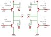
Below is the schematic. The resistors are 100 ohm, and the other end is connected to a PIC 16f88.

V+ is about 4.5V (3 C batteries)

Any ideas?
 

Attachments

  • hbridge_233.jpg
    hbridge_233.jpg
    45.9 KB · Views: 1,002
Hiya Adamthole,
The transistors your using only have a maximum continious collector current of 200 mA. Although you say your only using a small DC motor the current draw could be greater then the transistors can handle. Try using a bc337, bc 327 which have a collector current of 800mA and see if this makes a difference. I could be be way out on this but I made a H-bridge up a few years ago with a similar problem and by using the above transistors fixed the problem.

Hope This Helps

Cheers Bryan :D
 
Perhaps. Now that I think of it when I tested the amperage it read between 180mA and a little over 200mA...I will have to try that. Thanks!
 
MOSFETs are good too, but obviously it will need a different circuit. And you don't need to supply a lot of base current to them all the time to accomodate the max current it could need.
 
An electric motor is stalled when it starts. Stalled motors draw much more current than when they are running. The current might be 1A until it gets up to speed. If the voltage was any higher then the little transistors would have curled up and died. :lol:
 
just cause a tranny has a rated current of 200mA does not mean it cannot draw more. It can!!! and it will given the opportiunity, it too much is drawn then it will fuse.


You want more power, upp the voltage or the current. The stall-torque is faily high for all machine and you need to get over its inertia to get it really spinning.
 
I'm working on getting different transistors...but I was curious how it would work if I used all NPN? Would it work the same or worse? I read somewhere that the NPN's were better at sinking and the PNP's were better at sourcing. Is this true, and if so how much of a difference does it make?
 
Let's make the assumption that the motor is a small tiny, and wide piece of wire (more like a slice of wire).

It's resistance is (lets assume) 1 ohm.

Let's add a resistor in series, to make the load bigger than 1 ohm.

This will also drop the current requirements, and just maybe then can you get away with your transistors.

and why are the diodes connected between emitter and collector of the transistors?


And if you want an equation, use this:

Motor current consumption = (Supply Voltage) / (Motor's internal resistance + resistor you want to put in series with it).

Sure, you might notice a loss in speed, but it is well worth the money, and time.

From the top of my head, the resistor you should use should be at least 1/2 to 1 watt resistor with a value between 1 and 50 ohms.
 
NPN's are only better at sinking due to the way current flows through them
PNP are equally only better at sourcing due to the way current flows through them

I would go as far as saying NPN cannot source and PNP's cannot sink when in Push-pull arrangement
 
okay, that makes sense.

I've been playing around with switching the NPN transistor. using the 2n3904 the maximum current I could get it to put out (holding the motor so it wouldn't spin) was 330mA. When I switched to a 2n5088, that number increased to 390mA. I tried several other transistors, which were all between or lower than the above numbers. The weird thing is that the 2n3904 is rated at 200mA Ic, while the 2n5088 is rated at only 100mA Ic. Any idea why it would work better?

This is still using the 2n3906 for the PNP part of the transistor.
 

Attachments

  • 2n5088.pdf
    97.4 KB · Views: 288
You can't accurately measure current through transistors straining way above their max current ratings. Simply measure the resistance of the motor and use Ohm's Law with your battery's voltage (which is also probably dropping at start-up) to determine the max current.
Then you'll be looking for logic-level power Mosfets.
 
audioguru said:
Simply measure the resistance of the motor and use ohm's Law with your battery's voltage (which is also probably dropping at start-up) to determine the max current.

I just elaborated that in my last post. I even showed the equation.
 
i got excellent response on using irf z44n mosfets....
try them, they r gud and bears lots of current too.
 
When the battery's voltage drops to 3V then the Mosfets won't work. A simple voltage doubler circuit could be added to drive them well.
 
i want to use four n type mosfets as four switches in a h bridge ckt.
then i need to amplify the gate voltage of the top mosfet so that Vds becomes more than 4v.
a simple op amp doesn works{loading}
will a voltage doubler help????/
if yes, then plz post some link to it or some schematic......
 
You could get about +7.3V from +4V with a charge-pump IC:
 

Attachments

  • charge_pump.png
    charge_pump.png
    9.8 KB · Views: 697
hi,
thanks man....
can u jus lemme know wats the max. voltage i can give in at v+ and the max. current which the ic can bear....
 
addyismad said:
can u jus lemme know wats the max. voltage i can give in at v+ and the max. current which the ic can bear....
Look at its datasheet and application notes from links in Google.
 
hi ,
i tried tat configuration...
its giving me 7.6v for an input of 5v and 17.8v for 12v.
i want something aboout 12v from 5v {if possible}...
please help me out.
 
Status
Not open for further replies.

Latest threads

Back
Top