Continue to Site

Welcome to our site!

Electro Tech is an online community (with over 170,000 members) who enjoy talking about and building electronic circuits, projects and gadgets. To participate you need to register. Registration is free. Click here to register now.

  • Welcome to our site! Electro Tech is an online community (with over 170,000 members) who enjoy talking about and building electronic circuits, projects and gadgets. To participate you need to register. Registration is free. Click here to register now.

Generator overload protection

Status
Not open for further replies.

Chilli

New Member
Hi All,

Any ideas on how to build a generator (Diesel driven) Overload protection?
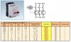
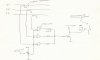
Basically what I want to do is to monitor the 3 phases and if there is a overload on any of the phases it should either disconnect the output or remove the exitation from the generator. The generator is rated 10kVA / 380V.
Design challenge??
Any help is appreciated
 
Use a thermal protection

something like the pic below

It's name, thermal protection, might be a bit misleading. It does not monitor the temperature of the load as some ppl think. The contacts inside the protection itself become a certain temperature (the more load, the hotter) and they release on a set current.

You should also place a normal short-circuit protection (...a Fuse) in series with the thermal protection.
 

Attachments

  • thermalProtect.JPG
    thermalProtect.JPG
    55.4 KB · Views: 1,734
Hi Exo,

Have these motor protectors a faster response time than circuit breakers?
I have a 15Amp circuit breaker currently installed but when I run a load from 1 phase with 20Amps it does not trip. (it will eventually i think)
The other problem is Vibration. As these thermal overloads are purely mechanical it is very likely for them to fail after some time.

I was thinking more in the line of a couple of current transformers, a couple of op-amps,a bit of PIC 16F84, and a lot of brainpower to help me slap this thing together. :lol:

Regards,
Chilli
 
I assume the generator has DC excitation, does it have a voltage regulator? What is the regulator circuit? The current sense could possibly operate on the regulator to shut the generator down.
 
YEs it does have DC exitation. I have been scratching my head in the meantime and came up with a circuit idea. I will just have to get it neatly drawn (yeah right) on a paper. I will post it ASAP.

Regards,
Chilli
 
It's not the neatest drawing around...............
I'll do better next time!
This is the basic idea I had in mind. I still gotta ponder with a couple of resistr values. I got myself three CT today!!!! I'll keep you updated on my progress. A PIC will be added in due course for other functions. So what do you say about this circuit idea? Any other solutions are welcome.


Regards,
Chilli
 

Attachments

  • genoverload.jpg
    genoverload.jpg
    23.1 KB · Views: 1,640
Keep in mind that the current xfmr outputs will be AC voltages. You should bias one end of each xfmr up to VCC/2, and you can't drive a relay directly from the comparator output. You'll need a retriggable oneshot, a latch, or something similar to hold the relay on. You should look at LM339, which is a quad comparator. It has open collector outputs, so you can wire OR the outputs and use a single pullup resistor (the output will be active low). You might need input resistors and shunt diodes to the supply rails to protect the comparators from overvoltage.
 
Warm Greeting fom Namibia,

Ron H,
The diagram is just a vague idea I had in mind.
OOOOpppps Ron H... what would I have done without you? You're right I nearly forgot that the xmfr was AC!! Thanks! I think in that case I'll just feed the op-amp through a 10nF cap and then bias it?
My intention is to use a CA3140 op-amp because of it's high input impedance(less load on the xmfr, therefore less error????) and secondly I can drive the input to within 2% of rail voltage. (thirdly 'cause in Namibia you don't get everything around the corner and I just happen to have a couple of them lying around somewhere LOL)
I would not drive the relay directly from the comparator but instead(for the time being before the PIC comes in) to rather use it as a trigger for a 555 "delay on" timer.
I've done a quick test on the xmfrs I got today and they all read differently when I run the sam load through them. Hmmmmmmm.......'will have to do some serious investigation............

Cu later

Chilli
 
Hi Guys,

Managed to get a design on breadboard. I will post it shortly. It'll blow your mind!!!!!!

Chilli
 
Hi Guys,


Check out the circuit !

Works beautifully


Chilli
 

Attachments

  • GENMOD.JPG
    GENMOD.JPG
    292.9 KB · Views: 1,504
Good work, Chilli. I haven't looked at the entire circuit, but I have a couple of observations:

1. I see no need for the capacitors in series with your current transformers. They have no DC bias, so they can be connected directly.

2. As Russlk said, current transformers are meant to be terminated into a low impedance load. With no load, you get very high voltages, which is probably why you are having to attenuate the hell out of them. Remember, they are, as the name says, current transformers. The primary is, I assume, one turn (your mains wire). Let's say you have 30 amps in the primary, and your secondary has 1000 turns (just an example). This will yield 30ma in the secondary. If you have a 100 ohm load, you will get 3 volts out. Also note that the low frequency cutoff of the secondary is Fc=Rload/(2*pi*Lsec), where Lsec is the inductance of your current transformer and pi=3.1416. Notice that, as Rload goes up, the low frequency cutoff goes up (higher is worse). If each transformer is working below the cutoff frequency due to high Rload, The voltage you get out, while very high, will be dependent on the inductance of the individual transformer, which can vary considerably from unit to unit due to the fact that the core permeabilities vary considerably from unit to unit. Inductance is proportional to permeability. If you load the transformer enough to get into the flat portion of the bandwidth curve, the voltage out will be only a function of the number of turns, which is precisely controlled by the manufacturer, and all transformers will match very closely.

Did any of that make any sense?

I also noted what may be just a drawing error. In the upper right hand corner, the anode of D1 is connected to the wrong side of the resistor.
 
Hi Ron,

Belive me I didn't have a 'cockin clue what you were trying to explain. :?

Im am by no means a expert, just a humble diesel mechanic!! LOL and no education in electronics, just about 15 Years of practical experience. I never bothered much about theory! (I suppose that's why you confused me?)

I built this circuit on breadboard and could therefore experiment with a couple of components. If I ommited the C1 - C3 it seemed like it does not want to work. I also thought that it could be that the input signal is AC and the op-amp would like to have some sort of positive signal only.
I tried to load the CT with a 100R resistor but then sweet ef all happened.
Actually weird!
Now did I confuse you??? Hehehehehehehe
Specifications on the CT are as follows:

Primary 30A
Secondary 5A
2.5 VA
No of Turns of Primary 3T

This is my basic idea of the circuit:
If you connect a scope to the output of the op-amps you will see a positive pulse whenever the voltage of the CT goes above Vref (Adj. by VR1 - VR3). This pulse I feed to a "Pulse stretcher" which is the first 555 Timer. Monostable with t=1.1*C*T (HA! See I knew one formula!!) which gives you round about 1.1 Seconds. You will see that it is re-triggerable.
The second 555 is configured as a "Delay ON" which gives you about 5sec
before finally triggering the third 555 which is configured as a "Flip Flop". Note it's "own" 0 V supply for the second timer.
The reason for the delay on is to compensate for Inductive (reactive) loads on the generator. The "Delay ON" timer" give you that extra time in the event of a momentary overload.

Thanks Ron for spotting the mistake! Youré 100% right. it is a mistake. :oops: 
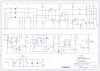
You got a Eagle eyes huh?

I really appreciate your input


Next step would now be to find a suitable enclosure for the circuit. But nowhere in South Africa (just south of us) can I find enclosures for DIN rail mounting. I stripped an old 11 pin relay housing and shove it all in there! Hehehehe

Regards,
Chilli
 
Your current transformer specs are strange. 30 amps/ 5 amps gives a ratio of 6 whereas standard ratio is 1000. If the primary rating is for 1 turn, then with 3 turns the max primary current is 10 amps for 5 amps out. That does not make sense, do you have a manufacturer's name and part number for the transformer?
 
Although on their spec sheet it says only 20A, on the ones I have it says 30A.
This is their webpage:

**broken link removed**

Check it out


Chilli
 
hey chilli,
i'm an undergraduate student looking for a project for my 6th semester. i'm into electrical and electronics engg:. so what i would like to ask you is....can i take up the generator overload protection as my project. at first i was gonna do electric field disturbance monitor but the prof rejected it saying that the circuit is simple. actually it was not. but what does he know.... so it would be really helpful if you can provide me with some details about this project. that is if it's o'k with you. but i need help real fast.... i've to submit my project topic in three days.
thanx.
dave
 
Hi David,

Thank you for your kind enquiry about using this circuit.
Ofcourse you can use it.
I cant really give you all the theory behind it but hey some prof or even some user here can help you out on this one. But I will try my best to explain to you. See the circuit theory on page 1 about this circuit.
I think Ron & Russlk can without doubt write you a long and intricate report :lol: ( gee these guys know their theory!)

Don't forget to mention that this circuit idea came from some poor bloke in Namibia. Hehehehehehehehe Just kidding!

Chilli

P.S. Note the drawing mistake on D1. As RON ( 'ol eagle eye) has spotted, the anode should be connected to the other side of R10.
 
There is another mistake on the diagram. D1-D3 should be connected with their cathode to the collector of Q1, Q7, Q8.

'ol eagle eye didn't spot that one! :cry:

Rgds,

Chilli
 
Status
Not open for further replies.

Latest threads

New Articles From Microcontroller Tips

Back
Top