Continue to Site

Welcome to our site!

Electro Tech is an online community (with over 170,000 members) who enjoy talking about and building electronic circuits, projects and gadgets. To participate you need to register. Registration is free. Click here to register now.

  • Welcome to our site! Electro Tech is an online community (with over 170,000 members) who enjoy talking about and building electronic circuits, projects and gadgets. To participate you need to register. Registration is free. Click here to register now.

Generating square waves of 0-5V voltage levels

Status
Not open for further replies.

km

New Member
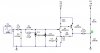
Hi there, I have a problem with my circuit. I suppose to get a square wave output with voltage levels 0-5V at point A, but when I test my circuit with the circuit maker simulation, it gives me a different answer. What should I need to do in order to get the desire output? :roll:
 

Attachments

  • circuit_142.jpg
    circuit_142.jpg
    20.3 KB · Views: 697
With "C4" in the output of the circuit, you have created an RC differentiator. With this in the circuit, you will see only pulses at test point "A", a positive pulse when Q2 turns on and negative one when Q2 turns off. JB
 
jbeng said:
With "C4" in the output of the circuit, you have created an RC differentiator. With this in the circuit, you will see only pulses at test point "A", a positive pulse when Q2 turns on and negative one when Q2 turns off. JB
The input is 1MHz. 47nF and 450k (1Meg || 820k) is a 750 Hz highpass. This would only be a differentiator for square waves in the range below a few hundred Hz.
Goodpickles, you'll never get 0-5v out of that circuit, because the power supply is only 5v. You can get close with the following changes:

R5=390
R4=1k
C3=47pF
R7=1Meg

With these values, my sim shows a 0.46v to 4.68v square wave (well, sorta square).
 
-

THanks Ron for all the values you gave!! It works :wink:

After the output, if I want to get a clean sqare wave, what should i do? Can I connect a "Quad 2 input NAND with schmitt trigger" ? :idea:
 
you could try a schmitt trigger made from an op-amp and some resistors, then you would be able to adjust the hysteresis to get a particular duty cycle (if you need it)

if you just need ANY sort of rectangular wave out of it, then you could use a comparator, or that NAND you mentioned (with inputs tied together... making it basically a schmitt trigger inverter)
 
You don't need to jump through so many hoops. The circuit below will give you a 0-5v square wave.
Be sure to connect +5V and GND to pins 14 and 7, respectively. Connect a 100nF cap from +5V to GND, as close to the chip as you can get it, and with short leads.
Connect all unused inputs to GND.
 

Attachments

  • limiter.gif
    limiter.gif
    3.8 KB · Views: 561
Thanks Ron. :wink:

Ron said:
Connect a 100nF cap from +5V to GND, as close to the chip as you can get it, and with short leads.

What you mean by that? and Whats that triangle connect to D2?

The circuit that you have gave me will it able to convert different amplitude and frequency of a sine wave to a 0-5V square wave with the same frequency?
 
km said:
Thanks Ron. :wink:

Ron said:
Connect a 100nF cap from +5V to GND, as close to the chip as you can get it, and with short leads.

What you mean by that? and Whats that triangle connect to D2?

It's an HT decoupling capacitor, in any high speed logic circuits you should fit one across each chip. You wouldn't usually bother drawing them on a circuit diagram, just as you don't usually show the HT connections to the chip.

The 'triangle' is a 'ground' symbol, the 0V connection of the circuit.

The circuit that you have gave me will it able to convert different amplitude and frequency of a sine wave to a 0-5V square wave with the same frequency?

Yes, it's a 'schmitt trigger', it converts the incoming signal to a square wave - with a sinewave input it will be the same frequency, with much more complicated waveshapes this won't always be so.
 
The triangle is a symbol for GND, or circuit common.
This will convert large amplitude sine waves (4v p-p to 20v p-p) into square waves at the same frequency. You never specified variable amplitude or frequency. Over what input amplitude and frequency range do you need it to work?
 
Status
Not open for further replies.

New Articles From Microcontroller Tips

Back
Top