Xavier Pacheco
New Member
Hi,
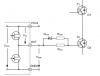
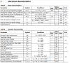
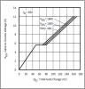
I'm trying to calculate the gate resistors for the MOSFET that I selected which has a gate resistance of 1.3 ohms. Well, I attach its electrical characteristics (Parameters.PNG). Also, I add the Vgs vs Total charge curve. I would like to find the suitable configuration for this application (See Gate1.PNG an Gate2.PNG). Some of the gate driver characteristics are also attached [GateDriverParameters.PNG].
The gate driver power supply is 12V.
The sink/source capability of the driver is 5A.
So taking into account the worst scenario where the charging current is equal to the peak current of the driver (5A)
RGon = 12/5 - (0.55 + 1.3) = 0.55 ohms
where 0.55 ohms is the Rds(on) or source resistor of the driver and 1.3 ohms is the mosfet gate resistance.
For the discharge current
ROff = 12/5 -(0.7 + 1.3) = 0.4 ohms
where 0.7 ohms is the sink resistance of the driver.
It's supossed that the charging peak current has to be less than driver peak current (5A). So, how do I know the real charging peak current?
Is this approach right?
In the Gate2.PNG picture, do I need the diode and the discharging resistor?
I'm really stuck at calculating the right gate driver configuration. I will appreciate your help so much.
Additional information:
PWM frequency (gate driver input) = 25 kHz
VDS is about 150-170VDC
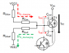
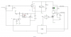
The application refers to a Brushed DC motor controller using low side switching as shown in attachment Scheme.PNG
Datasheet of the Mosfet: https://www.infineon.com/dgdl/Infin...N.pdf?fileId=5546d4625b3ca4ec015b3e42ba4a0744
Gate driver: https://www.mouser.com/datasheet/2/196/Infineon-2EDN752x-2EDN852x-DS--DS-v02_05-EN-1225984.pdf
Useful document about gate resistors: https://www.infineon.com/dgdl/Infin...N.pdf?fileId=5546d462518ffd8501523ee694b74f18
I'm trying to calculate the gate resistors for the MOSFET that I selected which has a gate resistance of 1.3 ohms. Well, I attach its electrical characteristics (Parameters.PNG). Also, I add the Vgs vs Total charge curve. I would like to find the suitable configuration for this application (See Gate1.PNG an Gate2.PNG). Some of the gate driver characteristics are also attached [GateDriverParameters.PNG].
The gate driver power supply is 12V.
The sink/source capability of the driver is 5A.
So taking into account the worst scenario where the charging current is equal to the peak current of the driver (5A)
RGon = 12/5 - (0.55 + 1.3) = 0.55 ohms
where 0.55 ohms is the Rds(on) or source resistor of the driver and 1.3 ohms is the mosfet gate resistance.
For the discharge current
ROff = 12/5 -(0.7 + 1.3) = 0.4 ohms
where 0.7 ohms is the sink resistance of the driver.
It's supossed that the charging peak current has to be less than driver peak current (5A). So, how do I know the real charging peak current?
Is this approach right?
In the Gate2.PNG picture, do I need the diode and the discharging resistor?
I'm really stuck at calculating the right gate driver configuration. I will appreciate your help so much.
Additional information:
PWM frequency (gate driver input) = 25 kHz
VDS is about 150-170VDC
The application refers to a Brushed DC motor controller using low side switching as shown in attachment Scheme.PNG
Datasheet of the Mosfet: https://www.infineon.com/dgdl/Infin...N.pdf?fileId=5546d4625b3ca4ec015b3e42ba4a0744
Gate driver: https://www.mouser.com/datasheet/2/196/Infineon-2EDN752x-2EDN852x-DS--DS-v02_05-EN-1225984.pdf
Useful document about gate resistors: https://www.infineon.com/dgdl/Infin...N.pdf?fileId=5546d462518ffd8501523ee694b74f18