Electro Tech is an online community (with over 170,000 members) who enjoy talking about and building electronic circuits, projects and gadgets. To participate you need to register. Registration is free. Click here to register now.
Welcome to our site! Electro Tech is an online community (with over 170,000 members) who enjoy talking about and building electronic circuits, projects and gadgets. To participate you need to register. Registration is free. Click here to register now.
When you say game buzzer, do you want a circuit that once button A has been pushed, and the corresponding light or buzzer sounds, pushing button B has no effect, unless the circuit has been reset.
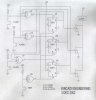
#1. The nor gates used have too many inputs. You can do the same circuit with a 3-input NOR gate.
#2. Since there is only one buzzer, this circuit is almost unnecessary. All you need to do is put any number of keys together (depending on # of players) in parallel. Connect it to +ve and the SET pin on the 4013 chip.
Connect the SET pin to -ve through a 1K resistor.
Connect Q to the output (buzzer or LED), then to ground.
Connect the clock to ground.
Connect data to ground.
now connect RESET to a key (which turns the output off), then to +ve. Connect RESET to -ve through a 1K resistor.
i built a big game buzzer in my vo-tech class once
it ran on 120v and the output was 3 100W bulbs
used some contacks, relays, wire and push buttons
it was wired so that if everyone puched the putton (there were 3 of these buttons) the first that was triggered would light and ther others would be locked out
This site uses cookies to help personalise content, tailor your experience and to keep you logged in if you register.
By continuing to use this site, you are consenting to our use of cookies.