Continue to Site

Welcome to our site!

Electro Tech is an online community (with over 170,000 members) who enjoy talking about and building electronic circuits, projects and gadgets. To participate you need to register. Registration is free. Click here to register now.

  • Welcome to our site! Electro Tech is an online community (with over 170,000 members) who enjoy talking about and building electronic circuits, projects and gadgets. To participate you need to register. Registration is free. Click here to register now.

Function_generator

Status
Not open for further replies.

endaya_walatch

New Member
hi.. can you help me to vary the frequency in this schematic?? i need to have a range of frequency of 6Hz-7 kHz.. urgent reply..please... thanks..
 

Attachments

  • function_gen.jpg
    function_gen.jpg
    63.9 KB · Views: 171
R1 and C1 set the frequency for the square-wave. Then the integrators filter out some of the harmonics and make a triangle and sort-of sine-wave.

The capacitors must be non-polarized but for your extremely low frequency they will be huge unless you use two electrolytic capacitors back-to-back for each one.
 
Even though the mulivibrator section can be varied in frequency as AudioGuru said, the filters which are intended to make puesdo sine wave are fix-tuned to one specific frequency, and will not work over three decades. If you need a sine waves, you should be looking at an intrinsically sine-wave oscillator, like a Wien-Bridge.
 
Last edited:
In fact, nothing after amp1 will work over the frequency range. Even the square gen, amp1, isn't configured correctly. There are good function gen. circuits, where all the signals work.
 
Last edited:
Even though the mulivibrator section can be varied in frequency as AudioGuru said, the filters which are intended to make puesdo sine wave are fix-tuned to one specific frequency, and will not work over three decades. If you need a sine waves, you should be looking at an intrinsically sine-wave oscillator, like a Wien-Bridge.
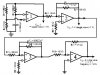
I agree, except for the fact that the AGC loop will take a long time to settle when the frequency is low. Direct digital synthesis is the clean way to do it, but is more complex. A function generator with a sine shaper , e.g., XR2206 is another way. Still another method uses a switched capacitor filter.
 
Agree with the previous posters.

Your circuit is only really suitable for operation at one particular frequency, or over a very narrow frequency range as it now is.

If you want to generate sine, square, and triangle waves over a very wide frequency range, use a commercial function generator chip such as the one Roff has already suggested.
These are low cost, very easy to use, and work well.
 
Aw, you don't need a commercial function gen chip, though that would be the easiest way to do it. I often don't take the easy way because I don't learn as much. I can search for a better diagram if you still want to build your own.
 
Last edited:
Well yeah.

But if you can buy a purpose built chip for two dollars that does EXACTLY what you want, and does it very well, why do it any other way ?
 
There are many different motavations for making your own circuits. You might do it because you can't get the functions you want ready-made. Conversly, you might want to learn how to use electronic components, and strengthen your learning by getting some "hands on" experience. Function gen circuits make great learning projects because they use many different electronic functions, multivibrators, integrators, etc. I've made several of these, and have yet to need a purpose built chip.
 
Very true Brownout, if the sine wave source is the entire project.

But I suspect it is just one building block of something far larger.

While it is entirely possible to build your own op amps and +5v regulators out of discrete transistors, and learn much in the process.
There comes a point where a quad op amp or 7805 saves a lot of time board space and money.
 
thanks to all of your replies..

just wondering of what audioguru said.. what do you mean of using 2 electrolytic capacitors back to back?? do i need to make it in series??

my main priority is to be build a function generator using 741 op-amp..
do you have a op-amp based function generator??

thanks...
 
i only have this schematic for 741 function generator... will i change the R1 to a potentiometer to vary the frequency??

please help me...

thanks
 
Two polarized electrolytic capacitors in series and back-to-back make a non-polarized capacitor with half the value of one.

Your extremely old and simple circuit makes a poor sine-wave with a single frequency. You might make it switch parts for other frequencies. Three capacitors and/or three resistors must be changed at the same time.

The 741 opamp is too old and slow to make high frequencies.

i've thinking of changing the R1 with a pot..and apply the 2 electrolytic in series like what you've said..

what do you mean by switching parts and what are those capacitors and resistors to change each time??

thanks again..
 
Yes, all those components ALL need to be changed when you change the frequency.

If you don't you will have massive changes of output amplitude and wave shape as you try to change frequency.
 
If you do not vary the filters the same as the oscillator then the "sine-wave" will turn into a poor square-wave or its amplitude will be reduced.
 
Very true Brownout, if the sine wave source is the entire project.

But I suspect it is just one building block of something far larger.

While it is entirely possible to build your own op amps and +5v regulators out of discrete transistors, and learn much in the process.
There comes a point where a quad op amp or 7805 saves a lot of time board space and money.

I don't deny that IC's save time, space and $$$. All I'm saying is if the sig gen is the project, and I believe it is, there is a good opportunity to learn alot about electronic functions. Most of the hobby sig gen designs use integrated op-amps anyway, and I think it's good to learn how to use these IC's. Right now, I have several of these projects on my bench. Even old designers like me need to go back to basics every now and then. Believe me, at my age, I need alot of refresh cycles.

One more reason I don't use alot of specific IC's in my simple projects is for replacement purposes. I do alot of experimentation. Translation: I blow up alot of stuff. I like the idea that I can grab a transistor or a 555 off my bench ( or from another project ) and quickly fix my home made grear. Don't have to stock any specialized chips.

The OP seems to want to make the completely inappropriate circuit design work for his purpose, rather than use one designed to be frequency variable. Hmmm... well, good luck on that :D
 
The amplitude stabilization parts for the Wien bridge Oscillator are similar to the parts that make an electric guitar sound fuzzy and nasty. Distortion.
 
Status
Not open for further replies.

Latest threads

New Articles From Microcontroller Tips

Back
Top