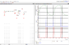
Sim looks like 25 Hz (10K ohms and .1 uF timing elements) -

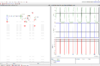
And at 200 Hz

Problem areas, output duty cycle, strong T dependence on gate threshold, strong T dependence of
passive values, noise immunity, in short its a crappy way of getting a well designed circuit.
Note using a Schmidt not much help as its thresholds vary all over the map as well. Better off using
a comparator and a reference to get predictable results.
Trimming RC values could get closer to 50% duty cycle, but overall circuit just poor. Not to mention
discharging cap thru internal CMOS structures on power down, known to create hot spots in die
and possible damage. One could add a series R with gate input between it and cap to prevent this,
buts thats tacky.
Regards, Dana.
And at 200 Hz
Problem areas, output duty cycle, strong T dependence on gate threshold, strong T dependence of
passive values, noise immunity, in short its a crappy way of getting a well designed circuit.
Note using a Schmidt not much help as its thresholds vary all over the map as well. Better off using
a comparator and a reference to get predictable results.
Trimming RC values could get closer to 50% duty cycle, but overall circuit just poor. Not to mention
discharging cap thru internal CMOS structures on power down, known to create hot spots in die
and possible damage. One could add a series R with gate input between it and cap to prevent this,
buts thats tacky.
Regards, Dana.
Attachments
Last edited:
