Continue to Site

Welcome to our site!

Electro Tech is an online community (with over 170,000 members) who enjoy talking about and building electronic circuits, projects and gadgets. To participate you need to register. Registration is free. Click here to register now.

  • Welcome to our site! Electro Tech is an online community (with over 170,000 members) who enjoy talking about and building electronic circuits, projects and gadgets. To participate you need to register. Registration is free. Click here to register now.

Frequency doubler circuit for variable input square wave?

Status
Not open for further replies.

GDCobra

New Member
Hi all, hoping someone can help out.

I'm looking for a circuit which will double the frequency of an input square wave.
The input wave has a 50% duty cycle (I'm told), 0-12v amplitude a and will vary from 25Hz -> 200Hz.
The output would ideally be 50% duty but amplitude could be 0-5v if that was more convenient. I'm assuming there would be some propagation delay as the output would not be 'known' until after the input cycle hence at least one cycle delay. This should be OK.

I'll give some background to the requirment as this may help the solution (or at least eliminate some).

The output is a tachometer signal from an electronic ignition system for a petrol engine. The standard output is 2 cycles per revolution (4 cyclinder, 4 stroke engine, coils fire twice), however this is being used on an 8 cyinder engine and its tachometer is expecting 4 pulses per revolution. OK, I could get a tachometer which requires only 2 pulses per rev' (or possibly even modify the one I have) but unfortunately this signal also feeds the fuel injection system which I don't have the facility to change or modify.

Ideally I'd like to NOT rely on the 50% duty cycle nature of the input signal as I'm taking this on trust but if it's the only way to make this work I'm happy to give it a go.

I have some electronics ability but a bit rusty. Any help greatfully received.
 
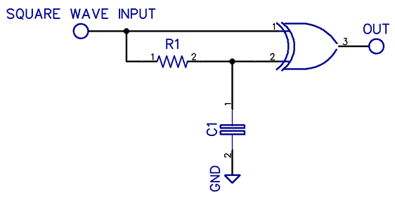
Use an XOR gate, a resistor and capacitor.
Please google: Xor gate frequency doubler.
The output signal however, won’t have 50% duty. Will that be a problem?

Otherwise you require a PLL, which will be more complex.
 
Use an XOR gate, a resistor and capacitor.
Please google: Xor gate frequency doubler.
The output signal however, won’t have 50% duty. Will that be a problem?

Otherwise you require a PLL, which will be more complex.

Thanks for the advice, I'll look into that.

I had seen some info' on using an XOR gate but thought that was for a fixed input frequency, must have got wrong end of the stick.

I don't think the duty cycle will be important, at the moment I think both devices (tachometer and EFi) only see a 'spike' anyhow.
 
I had seen some info' on using an XOR gate but thought that was for a fixed input frequency,
Only somewhat.
It just that the output pulse width of such a circuit is fixed by the input RC time-constant, so the output duty-cycle of the doubled frequency will vary with the input frequency.
And, of course, it should be apparent that the input frequency period can't be shorter than the RC time-constant pulse-width.
 
Last edited:
I am not totally clear about the situation. Are you trying to use a tachometer that is designed for a 4 cylinder engine on an 8 cylinder engine ? If so then you need to divide the frequency by 2 rather than multiply it by 2.

Les.
 
I am not totally clear about the situation. Are you trying to use a tachometer that is designed for a 4 cylinder engine on an 8 cylinder engine ? If so then you need to divide the frequency by 2 rather than multiply it by 2.

Les.


I'll try and clarify. Up until now the 8 cylinder engine has used a single coil with a distributor (prehistoric technology in my view!) this gets a pulse from the coil each time it is fired hence 4 pulses per revolution, this works with the current tachometer and EFi system.

I am now in the process of changing this to an electronic system driven by an ECU triggered directly from the crank and firing 4 coils (each linked to 2 spark plugs), there is still 4 ignition events per engine revolution but these are no 1 per coil hence no single point which I can use for the original signal.
The new ignition box I'm using does have a 'tachometer' output but this signal is evidently derived from the RPM (2 per revolution) rather than each time a coil is fired. So I do need to double the frequency, which is a shame as I'm sure it would be a lot easier to halve it! Just my luck.

Just for further information.
I have tried to 'sum' the ingnition pulses from the 4 coils using diodes, this did give a 'useable' signal with correct frequence but it also had a negative effect on the system causing rough running, almost a misfire.
I may try this method again but giving greater separation between the coil trigger lines from the ignition system and the output lines to the diodes.


Thanks for that, some useful looking options there. Unfortunately all based in USA, I'm in the UK, may not be any problem getting one shipped but will push the price up.
It's a pity I can't seem to find something similar in the UK, possibly due to 8 cylinder engines being relatively rare over here. Also doesn't help that I'm mixing different generations of equipment.
 
I have tried to 'sum' the ingnition pulses from the 4 coils using diodes, this did give a 'useable' signal with correct frequence but it also had a negative effect on the system causing rough running, almost a misfire.
I may try this method again but giving greater separation between the coil trigger lines from the ignition system and the output lines to the diodes.
Sounds like the load impedance at the diode outputs was too low.
Do you know what that was?
 
This is a possibility with a very small amount of code.

Basically chip counter measures frequency, that then is supplied to a DDS which generates 4X the
frequency, then is divided by 2 to produce an exact 50% duty cycle 2X freq output. System pretty
much does not care about input duty cycle as its edge detection for freq measurement.

Additionally there is an over RPM limit which is capable of shutting off ignition if it has a control input,
for motor protection.

Lastly there is a V proportional to freq output should that be an easier display interface. There are
OpAmps onchip if you need to scale the V to a specific range, or easier than that a couple of
additional lines of code to take care of that. Done with 12 bit DAC onchip.

Also onchip is a LCD controller in case you want to drive a LCD or LED or OLED type of display.

Right hand window shows many resources left in chip to use on other stuff. Like use its A/D to measure
V, other sensors like oil/temp/level for display in case you wanted to grow functionality of design.

1621444400166.png


Design tool (PSOC Creator) and compiler free, board for this $ 10 or $ 15. Depending on what
you want overall system to do.

I will try out above system in a couple of hours or so after I get some other work done.


Regards, Dana.

Post Followup : Seems to be working fine.
 

Attachments

  • 1621444048410.png
    1621444048410.png
    360.1 KB · Views: 305
Last edited:
Can you not just pull a signal off the crankshaft sensor used to trigger the ignition event?? It seems odd that the ecu could manage 4 ignition coils but not provide a decent tachometer signal also.

Can you provide a brand and model number of the electronic ignition conversion??

rfranzk
 
Still, use a PLL ... 25Hz to 200Hz is well within the capabilities with the right choice of timing capacitor and resistors to do what you want.

Here is a circuit simulator that shows in a block diagram the basic components of a PLL
 
Last edited:
The C-MOS IC 4046 has all components for an PLL, excluding a D-Flip Flop.
The signal from Your Ignition has to be conditioned possibly.
The D Flip Flop divides the signal / 2. So the PLL runs with double Frequency for further processing.

Another possible way is to use a Microcontroller, that meassures the Frequency and spit out the double of that.
But that has to be programmed!

When using IC's think for Overvoltage Protection of the Circuit.
 
I think the XOR edge detector method would be worth a try as the tachometer is probably not fussy about the duty cycle of it's input signal.

Les.
 
One change, added a buffer for the VDAC used for analog meter drive.
If you drive a bargraph or LCD bitmap display you can eliminate the
VDAC and its buffer. I set Max RPM alarm at 6000, you can set that at
whatever you want.

Code was ~ 10 lines of code, mostly start statements for each onboard
peripheral.

Keep this in mind for future projects, lots of fun, its like having a digital and
analog breadboard in one chip, and mostly drag/drop/config resources.

1621513167157.png


Regards, Dana.
 
The xor solution suggested by Schmitt Trigger in post #2 is the simplest and should work fine, as long as you set the pulse length so it's still relatively short at the highest input frequency.

You could use a 4093 quad schmitt NAND gate connected as an XOR, as in the diagram below; the schmitt trigger inputs will help clean up the input waveform and give reliable switching through the R-C delay.

300px-XOR_from_NAND.svg.png


(Drawing from the Wikipedia page here:
https://en.wikipedia.org/wiki/XOR_gate )

Once you have the XOR gate, this is the overall configuration, assuming an appropriate logic level input.
I'd try 10K and 0.1uF to start with & see how that works.

xoroctaveschem_1_orig.png
 
It will be interesting to find out whether a single RC value for the XOR approach will suffice over a 20-to-one input frequency range. Hopefully the characteristics of the tacho would allow this.
 
Indeed the advice of making a “discrete” XOR with a ST NAND is excellent.

It will be far more tolerant of imperfections on the input signal.

Since there are 4 gates per IC package, you will only require to use a single device.
 
Status
Not open for further replies.

Latest threads

New Articles From Microcontroller Tips

Back
Top