Continue to Site

Welcome to our site!

Electro Tech is an online community (with over 170,000 members) who enjoy talking about and building electronic circuits, projects and gadgets. To participate you need to register. Registration is free. Click here to register now.

  • Welcome to our site! Electro Tech is an online community (with over 170,000 members) who enjoy talking about and building electronic circuits, projects and gadgets. To participate you need to register. Registration is free. Click here to register now.

Frequency divider

Status
Not open for further replies.

beckmanb

New Member
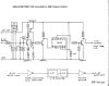
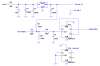
I am attempting to adapt a GM cruise control to my street rod. I have a pulse generator driven by the speedometer cable at 8,000 pulses per mile which is roughly eqivalent to 132 hz at 60 mph and between +2.v and -2..v ac sine wave. I need to divide this in half so I get 66 hz at 60 mph or 4000 ppm which is what the cruise expects. Attached is a circuit developed by ED Raether that I found on the internet (hope he doesn't mind me reposting in this forum) where he adapted a 40,000 ppm generator to the gm cruise. Would anybody be kind enought to take a stab at modifying it so it would work with the 8000 ppm sine wave I have.

Thanks in advance. Feel free to ask me further questions if clarification is needed.
 

Attachments

  • cruisepulsedividerschematic.jpg
    cruisepulsedividerschematic.jpg
    52.7 KB · Views: 1,241
If you can get your hands on an HEF4013, you should be able to do it like this. HEF4013 has Schmitt trigger clock inputs, which you need. If you can only get CD4013, you will have to have a separate Schmitt trigger such as CD40106 in front of it.

EDIT: You might need to add a 4.7k resistor from +5V to GND to meet the minimum current requirement of the 78L05.
 

Attachments

  • sine wave toggle.PNG
    sine wave toggle.PNG
    23.7 KB · Views: 1,788
Last edited:
Thanks Ron for the quick reply. I know the 78l05 is going to give me the 5 volts and I trust your circuit but I am just curious as to how the schmitt trigger acomplishes what I need. Also I note you put a .5-100 hz input. What happens if I go over 100hz? Another question is their a way to feed it to the second part to divide the frequency by 4? Also if needed is there an addon to the circuit where I could increase the output voltage up to a cutoff point of 5 volts? Sorry to be such a pain and again thanks for the help.
 
EDIT: You might need to add a 4.7k resistor from +5V to GND to meet the minimum current requirement of the 78L05.

I've never read that a 78L05 has a minimum current limit and never had to worry about that with the entire 78xxx series regulator family. Have you seen this somewhere Ron?
 
I've never read that a 78L05 has a minimum current limit and never had to worry about that with the entire 78xxx series regulator family. Have you seen this somewhere Ron?
It may not be a problem. I always defer to the specs.
 

Attachments

  • 78L05 minimum current specs.png
    78L05 minimum current specs.png
    37.7 KB · Views: 475
Thanks Ron for the quick reply. I know the 78l05 is going to give me the 5 volts and I trust your circuit but I am just curious as to how the schmitt trigger acomplishes what I need. Also I note you put a .5-100 hz input. What happens if I go over 100hz? Another question is their a way to feed it to the second part to divide the frequency by 4? Also if needed is there an addon to the circuit where I could increase the output voltage up to a cutoff point of 5 volts? Sorry to be such a pain and again thanks for the help.
The Schmitt trigger clock input just allows the flip-flop to use the sine wave input directly. The feedback from /Q to D causes the FF to divide by 2.
As I mentioned, the CD4013 is an equivalent part, but it has maximum transition time requirements around 10 microseconds. With a low frequency sine wave input, the clock would have to be squared up with something.
R3 and C2 form a lowpass filter to remove noise that might be present on the input. The hysteresis of the internal Schmitt trigger also helps in this regard.
I was thinking that you said your max input frequency will be 66Hz. I now remember that it is 132Hz. You should reduce the value of C2 to 2.2nF.If you want to run it faster than 132Hz, reduce the value of C2 to something like 1nF, or remove it entirely.
 
Last edited:
Ron

Thanks again. I think I am starting to understand. A couple of last questions - why do we add the 5v through r1 to the input and also tie input to gnd thru r2. Could it be made to divide by 4 by using the second flipflop/trigger?

Bert
 
Ron

Thanks again. I think I am starting to understand. A couple of last questions - why do we add the 5v through r1 to the input and also tie input to gnd thru r2. Could it be made to divide by 4 by using the second flipflop/trigger?

Bert
R1 and R2 form a voltage divider, biasing the clock input at 5V/2=2.5V. The 4V peak-to-peak sine wave input is AC coupled to this through C1, which causes the sine wave at the clock input (the junction of R1, R2, and C1) to swing from 0.5V to 4.5V. This is adequate to cause the flip-flop to toggle on each rising transition of the sine wave.
You could indeed divide by four by simply connecting /Q to D on the second FF, and connecting the Q (or /Q) output from the first FF into the clock input of the second one. You don't need a resistor in series for this connection.
 
Status
Not open for further replies.

Latest threads

New Articles From Microcontroller Tips

Back
Top