Continue to Site

Welcome to our site!

Electro Tech is an online community (with over 170,000 members) who enjoy talking about and building electronic circuits, projects and gadgets. To participate you need to register. Registration is free. Click here to register now.

  • Welcome to our site! Electro Tech is an online community (with over 170,000 members) who enjoy talking about and building electronic circuits, projects and gadgets. To participate you need to register. Registration is free. Click here to register now.

Free wheeling diode protection

Status
Not open for further replies.

burhanmz

Member
ok i've got a heavy inductive load to run (dc cap-start motor).. in order to protect the load i am using the free wheeling diode which basically protects my load from high current surges..

now i have look almost all over the net but haven't found anything on how to protect the free wheeling diode it self from momentarily high surges from the inductor energy when switch SW is open..

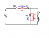
some books gave the circuit i have tried to imitate in red Ls, Rs and Cs... now i understand the purpose of Ls.. this will protect Dm and load from high surges from source...

but what i don't get is what Rs and Cs will do.. and if it will do some good then why not use another inductor in loop of Dm-Rs-Cs as depicted in blue.. so as to make an RLC circuit and control the damping?

and what would happen if i used a resistor (as depicted in blue) instead of Ls.

please help me clear my concepts.
 

Attachments

  • 11.PNG
    11.PNG
    13.3 KB · Views: 4,315
The RC network accros the diode will limit the dv/dt across the diode and keep it from breaking down in some situations. Most applications would not need this protection. Just use a diode with a high Vrev rating.
 
The free-wheeling diode is normally sized to momentarily carry the maximum motor current. Then the diode should not need any further protection.
 
It doesn't protect it from high current surges. It protects the switch from the inductive kickback that occurs when you suddenly disconnect current form an inductor- causing the inductor to dump it's stored energy. THe stored energy would preferably come mostly as current...but if it cannot find a path it will come in the form of mostly a voltage spike high in an attempt to force that current to flow. It's this voltage spike you want to supress since it damages things (usually the switch doing the disconnecting).

What would just a capacitor do? It would do it's best absorb/dampen the voltage spike to an extent (the bigger it is, the better it works). Remember it would absorb/dampen it, not clamp it like the diode. Okay, but the capacitor would die really quickly because currents tend to be too high for a reasonablely sized (and priced) capacitor of the type/quality that is needed. So you stick a resistor in to limit give the capacitor a way to dissipate the energy as well as to limit how much of the spike the capacitor tries to absorb. RCs are always on too, so they react very very instantly whereas a diode needs to turn on first.

The RC is not meant to protect the diode. If it is, then the diode is not suited for the job. It's supposed to supress the flyback in the short time period when the diode has not reacted yet. To further protect the switch. You can just use a diode or just use an "RC snubber". Only realy stringent cases require both.

You want to minimize Ls as it is part of the inductance (ie. move the diode and RC snubber as close to the switch as possible) producing the flyback that is damaging the switch.. Voltage spikes generated by Ls will not be clamped by the snubber since it is not in parallel with the snubber. Sure it will prevent large current ramps, but the load L already does that and flyback is not generated when inductances are powering up (they are absorbing energy in that case, not releasing it). Why would you add more the inductance that is causing the problem in the first place? It serves no purpose.
 
It doesn't protect it from high current surges.
What's the source of this high current surge? The only current I see is that through the motor.
 
The free-wheeling diode is normally sized to momentarily carry the maximum motor current. Then the diode should not need any further protection.

This post from Carl covers the requirement.

The current driving the motor at switch OFF, is the current thats going to flow thru the diode.
 
Status
Not open for further replies.

Latest threads

New Articles From Microcontroller Tips

Back
Top