Well, it looks like it would probobly work. The specifications are a little different for the FV1043, the diode capacitance is a little less, you might have to tweak the coil a little bit. The other datasheet here:
https://www.electro-tech-online.com/custompdfs/2003/05/MMBV2101LT1-DPDF.pdf --MV 2109
22 gauge wire should work fine, I would not change the # of turns, well maybe 2 3/4 turns, in stead of 2 1/2 turns. I used regular insulated wire, and it worked fine with insulation left on the wire. I tried 20 gauge and 18, I think 18 worked best.
One note, don't use a plastic transistor. Its not critical to use the 3904, any NPN will work, but I tried several, and the range was more than doubled each time I used a metal can transistor. I'm not sure why.
Circuit works best with a large metal base/ground. In fact, I built it in school on my metal based breadboard, and it worked much better on it than when I soldiered it together. But I didn't use ground plane.
The zener diode is not needed. the author only uses it to help regulate the battery power a little bit. It still runs on 9 volts. I used a regular 9 volt battery and it worked fine.
")
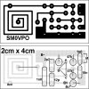
 I did not attach the schematic too.
")
 I have made a great step in electronics today