Continue to Site

Welcome to our site!

Electro Tech is an online community (with over 170,000 members) who enjoy talking about and building electronic circuits, projects and gadgets. To participate you need to register. Registration is free. Click here to register now.

  • Welcome to our site! Electro Tech is an online community (with over 170,000 members) who enjoy talking about and building electronic circuits, projects and gadgets. To participate you need to register. Registration is free. Click here to register now.

FM Transmitter Simulation Problem in Proteus Software

Status
Not open for further replies.
A whip antenna is usually a quarter of a wavelength long. Then its impedance is 75 ohms.
Use a 75 ohm resistor to replace the antenna in your simulation to make output level measurements and to see the actual waveform.
When the 75 ohms is removed from my simulation then the output level and waveform are completely different.
 
A whip antenna is usually a quarter of a wavelength long. Then its impedance is 75 ohms.
Sorry AG but I must strongly disagree with you on that point.

A halfwave dipole will have an impedance of 75 Ohm at its resonant frequency.

A quarterwave monopole mounted above a groundplane has an impedance of 35 Ohms at its resonant frequency.

An odd length of wire connected to some odd circuit board will have who knows what impedance.

JimB
 
I do not have a "perfect ground plane" for my whip quarter-wave antenna because it is just my hand. Then the impedance is increased from the 35 ohms to 50 or 75 ohms. My antenna has the correct length (75cm to 80cm) for the FM broadcast band.
 
Why the starting part of the waveform is in flat form? Here I attached my asc.file. So, can you help me to correct any wrong counting value of the component?
 

Attachments

  • Draft1.asc
    3.6 KB · Views: 186
  • FM Transmitter.JPG
    FM Transmitter.JPG
    47.6 KB · Views: 290
  • Before zoomed out.JPG
    Before zoomed out.JPG
    83.8 KB · Views: 271
  • After zoomed out.JPG
    After zoomed out.JPG
    99.3 KB · Views: 247
Last edited:
You have the simulation beginning at the start but it takes time for the signal of a sinewave oscillator to build up. My simulation has a delay at the beginning.

The antenna is an impedance to ground, not in series.
Your value for C7 was not calculated correctly so it attenuates the signal.
Your value for C3 is way too small for audio.
I also changed a couple of resistor values.
 

Attachments

  • transmitter.png
    transmitter.png
    40.8 KB · Views: 371
Sorry AG but I must strongly disagree with you on that point.

A halfwave dipole will have an impedance of 75 Ohm at its resonant frequency.

A quarterwave monopole mounted above a groundplane has an impedance of 35 Ohms at its resonant frequency.

An odd length of wire connected to some odd circuit board will have who knows what impedance.

JimB
I've learnt not to argue with AG... He may not tolerate certain individuals, but he definitely knows his stuff..
 
I've learnt not to argue with AG... He may not tolerate certain individuals, but he definitely knows his stuff..
I am not arguing with him, I am just point out where he is wrong.

JimB
 
If you build the circuit then you will find that the audio will sound like little high pitched squeaks because the small value of C3 will not pass low audio frequencies.
The value of C4 is 150nF for 75μs of pre-emphasis for North America. 100nF is used for 50μs in Europe and Australia.
 
I do not have a "perfect ground plane" for my whip quarter-wave antenna because it is just my hand. Then the impedance is increased from the 35 ohms to 50 or 75 ohms. My antenna has the correct length (75cm to 80cm) for the FM broadcast band.

No, the impedance of a 1/4λ whip operated against a tiny PCB-ground-plane is totally unpredictable, especially when the dimensions of the PCB are a tiny fraction of 1/4λ at the operating frequency. The field strength produced by a 100MHz mono-pole without a 1.5m by 1.5m ground-plane under it is more than 20db below what a either mono-pole operated against a proper 0.5λ x 0.5λ ground-plane, or a 0.5λ center-fed dipole would produce.

Relying on capacitance to couple to the hand/arm of a user to create a "counterpoise" for a mono-pole antenna has been extensively studied by the makers of VHF commercial/ham two-way radio handie-talkies, and the best ones are still >10db below an end-fed omni-directional vertical 1/2λ dipole (which do not require a counterpoise)...

Notice that he goes by audioguru; not RFguru...
 
My FM transmitter has a good range when its whip antenna is hanging out my window and nothing is grounded near it.
Its range is across the street to an FM "transmitter" from The Dollar Store.
About 200m down the street to a cheap clock radio or my Sony portable Walkman FM radio.
It is 2km across a large river valley to my very sensitive home stereo and car radio.

All that proves is that you have more than 20db of fade margin over these radio paths.
 
V2 is an audio signal of 100Hz. You have the TRAN (at the bottom) setup to see 100MHz. In my simulation I have TRAN set as .tran 0 180m 120m 50m to see the 100Hz input audio signal, and the output of Q1.
The value of C3 is still much too small. Use 0.33uF (330nF) which is 33 times the value of your 0.01uF.
 
Can this receiver circuit detect the transmitted wave from my FM transmitter and produce sound through the loudspeaker?
upload_2016-11-7_18-54-5.png
 
The two transistors are not biased properly and they are not an FM detector anyway so they do nothing.
The old 741 is an opamp that has an output current that is too small to drive a speaker. It is also is not biased properly and does not have any negative feedback so it will not work.

The original circuit you copied from **broken link removed** in India has the same transistor circuit that does nothing but it almost correctly uses an LM386 power amplifier that has built-in biasing and built-in negative feedback. It is missing an important resistor in series with the capacitor to ground on the output that is shown in the datasheet of the LM386. The comments on that website say the circuit does not work. I think most circuits on that site do not work. It copied a circuit of mine but changed a few things that made it not work.
 
Can I know how your circuit works and its schematic diagram?
I never built an FM radio. I buy good ones and poor ones. The FM radio from The Dollar Store is very poor. My clock radio and Sony Walkman radios are not bad but not good. The good ones are excellent.

Are you asking about how my FM transmitter circuit works? Then you need to learn about electronics.
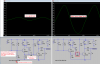
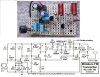
Somebody posted a defective FM transmitter circuit that they found on the internet. I looked at its schematic and explained why it did not work but they did not believe me so I fixed its 4 problems, one at a time:
1) Its mic preamp transistor was poorly biased so it was saturated and did not work when there was a new 9V battery and the transistor was cutoff and also did not work when the battery voltage ran down a little. So I biased it correctly and added a voltage regulator.
2) The radio frequency changed as the battery voltage ran down. So I powered the FM oscillator from the voltage regulator that I added.
3) The radio also frequency changed when something moved towards or away from the antenna. So I added an RF amplifier transistor to isolate the FM oscillator from the antenna.
4) The sounds were muffled with no high audio frequencies when heard on any FM radio. So I added pre-emphasis (treble frequencies boost) like all FM radio stations have that matches the de-emphasis (treble frequencies and hiss reduction) like all FM radios have.
I called my project "FM tx mod4" and here it is:
 

Attachments

  • FM tx mod4 pic and schematic.jpg
    FM tx mod4 pic and schematic.jpg
    196 KB · Views: 310
Status
Not open for further replies.

Latest threads

Back
Top