Continue to Site

Welcome to our site!

Electro Tech is an online community (with over 170,000 members) who enjoy talking about and building electronic circuits, projects and gadgets. To participate you need to register. Registration is free. Click here to register now.

  • Welcome to our site! Electro Tech is an online community (with over 170,000 members) who enjoy talking about and building electronic circuits, projects and gadgets. To participate you need to register. Registration is free. Click here to register now.

FM Transmitter Simulation Problem in Proteus Software

Status
Not open for further replies.
In school or university the electronics course will be taught about an FM radio circuit. In Google I looked for a circuit and found many simple and poor ones.
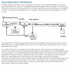
Here is the block diagram of an FM radio but you must understand about electronics to see how the blocks are designed and made.
 

Attachments

  • FM receiver.png
    FM receiver.png
    73.8 KB · Views: 218
After I constructed my FM transmitter circuit on a breadboard,I found that the third transistor Q3 had an easily heating problem. So, how to solve it?
 
After I constructed my FM transmitter circuit on a breadboard,I found that the third transistor Q3 had an easily heating problem. So, how to solve it?
The simulation shows the 3rd transistor averages 72.5mA and 7.2V= 529mW of heat which is a lot for the little transistor. The collector has a small output swing because its input level is low because the value of C7 is much too low. You should learn how to calculate capacitor values and their loads. The current in the transistor can be reduced to 34.2mA by reducing the base current by increasing the value of R9 to 47k then the collector voltage is about 7.7V and the heating is 34.2mA x 7.7V= 263mW which is much less than before.

The simulation assumes that your transistor has a "typical" hFE that might not happen in reality. The biasing of the transistor is so simple that transistors with low hFE will conduct a low current and transistors with a high hFE will conduct a high current.
Please increase the value of C3 as I asked a few times before and have R1 connect to ground.
 
Is there anything needs for changes? Can R9 value increase up to 78kOhm?
You forgot to add a 1ooopF or 2000pf ceramic capacitor from +9V to ground since the 47uF electrolytic capacitor C2 works well for audio frequencies but it has inductance that makes it useless at radio frequencies. The Sim program does not know that.
Your parts and battery are not connected to ground.
Didn't you simulate it with 78k? When I did the battery current, 3rd transistor heating and output power all were reduced:
 

Attachments

  • transmitter witrh 78k.png
    transmitter witrh 78k.png
    53 KB · Views: 198
Is this schematic correct? When I test the output frequency at the antenna of the circuit on a breadboard, the generated frequency was undergone unstable state where its value keeps on changing and sometimes it gets Giga Hertz frequency. What is the reason that leads to this problem? Is it because of using inductor coil or other else? Hence, it is hard for me to detect the input sound from microphone by using an FM radio.
upload_2016-11-10_17-28-42.png
 
A solderless breadboard has too much capacitance between its rows of contacts and wires for the very high frequency of 100MHz where 4.7pF is a capacitance. The circuit must be built compactly on a pcb or on Veroboard (stripboard) with its strips cut as short as possible like I did. I spaced my coils a few mm above the stripboard.

C6 and C8 are supposed to be trimmer capacitors so that C6 can be adjusted for the radio frequency and C8 can be adjusted for the most output power. I used 5pF-35pF trimmer capacitors in my FM transmitter.
R1 is not used if you build the circuit but the simulator needs it.

Your schematic does not show a microphone and the resistor needed to power the Jfet inside an electret microphone. The output level from an MP3 player is much too high and will need attenuation.
 
Status
Not open for further replies.

Latest threads

New Articles From Microcontroller Tips

Back
Top