Electro Tech is an online community (with over 170,000 members) who enjoy talking about and building electronic circuits, projects and gadgets. To participate you need to register. Registration is free. Click here to register now.
Welcome to our site! Electro Tech is an online community (with over 170,000 members) who enjoy talking about and building electronic circuits, projects and gadgets. To participate you need to register. Registration is free. Click here to register now.
Am now about the build my fm transmitter and I have one question before i start. When building the fm transmitter do I need a custom PCB board or any one from RadioShack will do just fine?
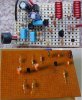
I built my FM transmitter on Veroboard. I carefully planned the parts placement so each wire is less than 1cm long. It works fine.
Other guys said their transmitter didn't work. They had parts far apart all over the place.
See the difference, and mine had many more parts>
I built my FM transmitter on Veroboard. I carefully planned the parts placement so each wire is less than 1cm long. It works fine.
Other guys said their transmitter didn't work. They had parts far apart all over the place.
See the difference, and mine had many more parts>
For someone with zero soldering skills, do you recommend me to do my project on the Veroboard or am I better off with PCB? Also how did you solder the bottom? Do you have a pic of that as well?
Veroboard has strips of copper that I cut to the proper length with a drill bit, then I soldered all the parts and a few jumpers to it. Sorry, no pic.
Practice soldering. Practice more soldering. Practice more and more soldering.
PCBs are much easier to solder. I avoid crappy Veroboard as much as possible. I always make PCBs for everything I make even if it's a prototype. If I'm unsure about about part of the circuit and I have several ideas I'll make the layout as flexible as possible, by leaving spaces where I might put a resistor or capacitor. In some cases I'll leave some strips or spots so I have a small Veroboard area I can work on, but I haven't built an entire project on Veroboard for a long time.
just want a simple fm transmitter but just want it to run of the battery of the mp3 player. which is running of a 1.5 AAA battery. i seen them made before but do not have the schematic, the power seem to come from the the audio jack of the FM transmitter. just want a mono type , just for listening to audio books on the radio.
thanks for the replies have search around the net but al the transmittters seem to run of a separate power supply
Have you ever though about looking at the origional circuit and using ohm's law to scale the resistor values down so a similar current is drawn at 1.5V? You might need to experiment a little but it might just work.
Do you want to use a simple lousy FM transmitter? Powered from the sound?
Why not just use a little amplifier and speaker? It could have its own battery because a tiny AAA cell has hardly any power.
yea just a lousy transmitter. like the ipod has one similar. it does not go far. works of the power of the head phone jack. must find out how much power comes out of the headphone jack and see if it is enough to transmit 5 metres. some power comes out of the head phone jack
It took me anout 1 minute to make my inductors and another minute to sand off the enamel at the ends. I don't think anyone sells inductors so simple and cheap. I just copied this one from another FM transmitter project:
Tried building a transmitter but it isn't working. I'm out of ideas and stuck now. One thing I found out was that my 9 V battery is oscillating at 80-89 MHz, that must be why it doesn't work.
Audioguru,
Does it matter what kind of capacitors/resistors used? I'm building your Mod 3, but nothing is working. Might be because of my inductor. I just used some cheap wires to wound it; it bends very easily. If you have any tips please let me know. Maybe I'll just build your mod 4.
Tried building a transmitter but it isn't working. I'm out of ideas and stuck now. One thing I found out was that my 9 V battery is oscillating at 80-89 MHz, that must be why it doesn't work.
A battery doesn't oscillate. The voltage could jump around at an audio rate if the battery doesn't have a 100uF bypass capacitor across it and its voltage might jump around at 100MHz if it doesn't have a 1000pF ceramic disc capacitor across it.
Does it matter what kind of capacitors/resistors used?
Of course it does. Many radio circuits need ceramic disc capacitors because they have very low inductance. Wirewound resistors are also inductors and cannot be used.
Make it like mine. Use ceramic disc capacitors and very short wires. Another guy made a much simpler FM transmitter with its parts spread out and it didn't work. Here are pics for a comparison:
For the inductors I can used any type of wire to wound it right?
What I was getting out of my transmitter(mod 3) was exactly what was coming from the battery, (89 MHz of noise). Took me about three hours of trouble shooting to figure that out. (Gained some good amount of soldering skills)
So to get rid of this noise you recommend a 1000pf ceramic capacitor accross the battery including the 100uf capacitor. I was thinking about a simple RC filter before the circuit to filter out the noise.
How much better is mod 4 compare to mod 3? Also what type of IC chip is it, is something I could buy at Radio Shack?
Use 1mm enamelled wire like I did or your transmitter probably won't work. I got my wire from a 2-way speaker's crossover coil.
A battery doesn't make noise at 89MHz.
An RC filter will just reduce the voltage to the circuit.
My Mod3 transmitter drifted its RF frequency as its battery ran down. Mod4 has a 5V low dropout voltage regulator to fix the drift.
RadioShack overcharges for the few simple parts they sell. Any real electronic parts distributor has low dropout voltage regulators.
your transmitter will oscillate as long as the power supply is connected because C5 is the main component on oscillation process, a part of the signal from the output collector of Q2 is feed to emitter of Q2 by means of C5 while trimmer capacitor C4 and L5 determines the oscillation frequency from 88mhz to 108mhz.
This site uses cookies to help personalise content, tailor your experience and to keep you logged in if you register.
By continuing to use this site, you are consenting to our use of cookies.