Continue to Site

Welcome to our site!

Electro Tech is an online community (with over 170,000 members) who enjoy talking about and building electronic circuits, projects and gadgets. To participate you need to register. Registration is free. Click here to register now.

  • Welcome to our site! Electro Tech is an online community (with over 170,000 members) who enjoy talking about and building electronic circuits, projects and gadgets. To participate you need to register. Registration is free. Click here to register now.

FM receiver

Status
Not open for further replies.
1MHZ is about worst case scenario, like if its a really hot day and i put it in an air conditioned room. If the temperature stays the same from turning it on to a couple days later, I never have to fiddle with tuning the receiver.

I don't think I would like AM because there would be more bulky I would imagine.
 
Yeah, 5 regular FM stations fit into 1MHz, but they are spaced further apart to avoid interference in cheap radios. If you used a narrow-band IF the 1MHz drift would include about 100 narrow-band stations. It would appear to make the drift 20 times worse.

I was mistaken before, adding a dual conversion mixer and new 455KHz IF would require you to turn-down your transmitter's input so the volume would end up the same, BUT, the radio would be much more sensitive to weak signals 'cause it would have more IF amplification.

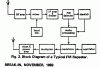
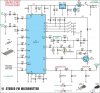
I looked into Google at the TDA1083 IC that is in your radio. It is a Telefunken "one chip AM-FM radio and speaker amplifier". Its datasheet shows two radio circuits, one with many extra parts that seems to be not very good, but not bad. The other radio circuit is very simple and its performance is, uh, you know.
He, he which circuit do you think is in your radio? If it is a Telefunken radio, it probably "won't be very good, but not bad". It's not a Telefunken, is it.

Look how much range NASA and now the europeans get with their space probes. I know how huge their receiving dishes are, but they must have RF amplifiers and IF strips coming out of their wing-wang! I bet their transmitters are pretty good too. Of course they use very accurate crystals in both.
 
It's not a telefunken. It doesn't say a thing about telefunken on it, it is made by emerson. It's a "super sensitive" fm/am radio :lol:. I looked at those schematics and it has to be the more complicated one because on the schematic there are 6 tunable IF transformers.

I think I first need to get a better idea of the stages in the FM receiver. Is this basically what a receiver looks like accept for the repeater part?

EDIT: I probably won't be able to post anything until Sunday because I'm going to lake Tahoe to go snowboarding, YEAH! :D
 

Attachments

  • typical_fm_rptr.gif
    typical_fm_rptr.gif
    9 KB · Views: 1,404
Hi Zach,
The radio's IC is made by Telefunken or is a Chinese copy. Emerson doesn't make anything, they just order Mexican or Chinese stuff with their name on it.
Look closely, your Emerson radio might even say, "Emersin" or "Super Sinsetive". If it says, "Made in USA", don't believe it. Usa is a town in China. Ha, ha.

When I was about your age, AM radios had 6 transistors in them. One radio said on its cover, "14 TRANSISTOR RADIO". Inside, it had 7 transistors all connected together but not connected to anything else! One transistor was used as the detector diode.

Very important parts in your radio would be an FM RF amplifier transistor or Mosfet and a tuned circuit that feeds it. I doubt it has the tuned circuit. It probably also doesn't have AGC for the RF transistor to reduce overload, so doesn't have much RF gain.
 
I'm getting the feeling that maybe I should just build my own receiver?

There are two transistors in my radio.

is that block diagram that i posted correct? I would like to know exactly what I am doing.

I'm sure that my transmitter dirfts a tiny bit. How much of a pain would it be if it drifted even a little bit? would I constantly be trying to get the signal? In other words, will I need to make a better transmitter?
 
Hi Zach,
The BH1417 is a stereo FM transmitter IC that uses a crystal and Phase-Locked-Loop for solid frequency stability. Kits-R-us (Hong Kong) might have a kit using it by now. An expert tested it and reports that its frequency is rock-solid but it has high distortion.
Silicon Chip (Australian magazine for electronic hobbiests) has a project for it showing a DIP IC. The manufacturer (Rohm Corp.) of the IC says it is surface-mount only. Go figure! https://www.siliconchip.com.au/cms/A_30378/article.html

Here's a nice little stereo FM transmitter kit that uses a microprocessor. This link has many pages about it:
**broken link removed**
 
The rest of these guys like to tell you the super-technical information. Since I'm working on the same thing myself, I have found two websites that solve your problem.

To access the first site, do a search for "superregen" on google.com and you should find a link which starts with **broken link removed** (or something like that). Once you access it, you will find a receiver schematic made by Rick Andersen.

But, wait... there is a better one.

Go to jbgizmo.com (I think it is .com) and access his VHF tracking receiver.
that design works better for me.

So basically, what you need is a detector (the above sites provide that), some simple amplifiers, and a power amplifier. OR, if you dont have 1 minute, you "could" try to hook the detector to your "microphone" input on your computer and listen to the radio through that, but I cannot guarantee that it will work.

Make the feedback resistors in the amplifier between 400K and 1500K.

if you need information on amplifiers, check out Harry's Homebrew page. Once again, search on google.com for it.
 
Super-regen radio, Ha.

Sorry that Silicon Chip wants you to pay to see their article.
Search Google for stereo FM transmitter. On page 6 you will have a free link to the whole project. Here's its schematic:
 

Attachments

  • silicon_chip_st_fm_transmitter.jpg
    silicon_chip_st_fm_transmitter.jpg
    108.8 KB · Views: 1,875
I think he was looking for a circuit to an FM receiver, NOT an fm transmitter.
 
Hi MS,
Zach's transmitter is just a toy. (Sorry, Zach).
The Silicon Chip transmitter project uses a crystal and Phase Locked Loop for rock-solid radio frequency stability. It also must have a very strong RF output because Silicon Chip added an output attenuator. Zach could bypass the attenuator for very good range.
The IC costs only about $2.90US and I think it is exactly what Zach needs. It only has high distortion when in stereo, it is fine in mono which is how Zach will use it.
Of course, Zach also needs a good sensitive radio.
 
damn you audio guru!! :lol: I was gonna scan my magazine to post on these forums that circuit diagram. :x

I have that kit sitting right next to me ready to be built, its just that i dont have the correct soldering tip for that smd chip. :(
 
Hi Pike. G'day, mate!
He, he. My jpeg digital copy is probably clearer than your scanned one will ever be.
Let us know what its distortion sounds like.
I recently noticed that its simple "brick-wall" low-pass-filter not only doesn't reduce input audio frequencies near 19KHz very much, causing beating distortion, but it also reduces audio frequencies above only about 6KHz. I figure that the frequency response at 15KHz is down about 5dB.
Also let us know what this high frequency loss sounds like and here's another one, Pike:
 

Attachments

  • micromitter_composite_marked.jpg
    micromitter_composite_marked.jpg
    91.6 KB · Views: 1,095
Hi everyone, sorry I was gone for so long, like I said, I went to Tahoe. It was sweet, I went off some jumps and stuff for the first time. Anyways, back to business.

mstecha, I like that circuit that second link that you provided there. It has an audio amplifier and a stereo jack, so why are you saying that it needs to be amplified?? I only want to listen to it with headphones btw. And this is the kind of radio that I am looking for, correct? Much more sensitive than a regular ol' car radio?

audioguru, will I have to have a crystal, PLL transmitter foresure? Let me just put it this way, on a regular radio, the transmitter does NOT drift.

And remember, I DONT HAVE ROOM FOR A BIG TRANSMITTER!!! :lol: . It would be so unbelievable cool if I could use the "toy" transmitter that I have with a super sensitive radio . . . It would be like a dream come true for me. Not only because it is small, but also the batter life is much better.
 
Do a search for an FM transmitter on google and you will see 1,000+ answers.

I'm saying amplify the signal because if you don't you might not be able to hear it through the headphones either.

Radio signals are very small to start with.
 
Hi mstecha.

I'm not sure what you meant by amplify the signal. Do you mean amplify the transmitter signal or the receiever signal?

I already have a 3v "bug" FM transmitter that seems to work very well indeed. I can get a range of 100 meters or so with a piece of junk clock radio. I am not interested in making a better transmitter, only a better receiver.

Just how much more sensitive is that radio that you provided than a regular radio?

Thanx for bearing with me :lol:
 
Hi Zach,
I think Mctechca's "some wonderful glorious super sensitive radio" is the super-regen that he modified and posted awhile ago.
It is the single transistor at the left side of his schematic:
 

Attachments

  • super-regen_cct.gif
    super-regen_cct.gif
    3.6 KB · Views: 1,099
Hi Zach,
Things wrong with a super-regen radio:
1) Its selectivity is terrible because a super-regen has just a single tuned circuit. It is also overloaded easily by stations it is not tuned to. A real radio has many tuned circuits.
2) Its noise level is high and it overloads easily by the station it is tuned to because it is oscillating all the time (quenched, in bursts).
3) The bandwidth is too narrow for proper FM broadcast reception, with lots of distortion, because it "amplifies" with positive feedback instead of gain.
4) It doesn't even have an FM detector. It is basically an AM radio that detects the amplitude change of the changing frequencies of an FM signal when the station is tuned to the slope of its tuned circuit. Therefore it is more sensitive to AM interference (tuned at the peak) and less sensitive to FM (tuned to one side).
5) It picks-up all kinds of static and other interference that is ignored by the limiter and FM detector of a real FM radio, because it has an AM detector.
6) For it to be sensitive you must fiddle with its sensitivity control (amount of positive feedback).
7) The super-regen's audio output fades away and gets very difficult to tune and re-tune as its tuned signal gets weaker. That's why Mstechca needs an audio amplifier with a lot of gain. Its noise level stays the same. A real FM radio's audio level stays the same as its tuned signal weakens (but its noise level increases).
8) A real FM radio's noise level decreases with increased signal strength, because it has lots of gain and limiting. So a signal that is only just a little stronger than what is barely detectable is heard without noise (quieting).

There are probably more things wrong with a simple super-regen that I can't think of.
Notice that the purpose of the original project was as a cheap tracking receiver for a transmitted tone, not music or speech. Quality (low noise and distortion) didn't matter. Just another "wonderful glorious super sensitive radio".
 
wow :lol: that sounds a little scary

SO WHAT DO I DO!?!? I do NOT want to make a better transmitter, I simply want to be able to hear my transmitter from farther away with a more sensitive radio. It seems that we've been going around in circles!
 
Status
Not open for further replies.

Latest threads

New Articles From Microcontroller Tips

Back
Top