Hey guys,
I am trying to control a solenoid that controls the flow of power steering to my steering rack on this race car I have.
Currently the car controls the flow based on speed, engine rpm, and steering angle. As you can imagine this is not ideal on a race track. Having it change all the time is disconcerting.
I have attached a few pictures:
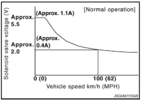
The first picture is the voltage and amperage range the car uses to control the flow. I need to match these.
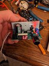
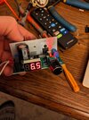
The other two pictures are of an LM317 board I picked up showing the minimum voltage range and the highest voltage range I wish to use.
Will this work?
I have a bit of a stupid question: When I hook up my meter to the output of the LM317 I always get 5A. No matter where I put the voltage it is always 5A. When I hook this unit to the actual solenoid will the amperage vary along with the voltage because of Ohm's Law?
I know the position of the solenoid is what is important. Wattage to solenoid is the most important. Do I need a rheostat along with the LM317 to control the amperage output as well? The graph shows very low amperage output. I attempted to hook up a 20 OHM rheostat in a way that controls the current, however, that only gave me a range of between 4-5A unless I was wayyyy on the bottom end. There I could barely control it between like 2-4A but it was jumping all around all over the place. I imagine that will be very bad for the solenoid.
Should I be using something completely different? Am I approaching this all wrong?
I will read and appreciate all comments, opinions, and roasts of my lack of electrical prowess.
Thanks!
I am trying to control a solenoid that controls the flow of power steering to my steering rack on this race car I have.
Currently the car controls the flow based on speed, engine rpm, and steering angle. As you can imagine this is not ideal on a race track. Having it change all the time is disconcerting.
I have attached a few pictures:
The first picture is the voltage and amperage range the car uses to control the flow. I need to match these.
The other two pictures are of an LM317 board I picked up showing the minimum voltage range and the highest voltage range I wish to use.
Will this work?
I have a bit of a stupid question: When I hook up my meter to the output of the LM317 I always get 5A. No matter where I put the voltage it is always 5A. When I hook this unit to the actual solenoid will the amperage vary along with the voltage because of Ohm's Law?
I know the position of the solenoid is what is important. Wattage to solenoid is the most important. Do I need a rheostat along with the LM317 to control the amperage output as well? The graph shows very low amperage output. I attempted to hook up a 20 OHM rheostat in a way that controls the current, however, that only gave me a range of between 4-5A unless I was wayyyy on the bottom end. There I could barely control it between like 2-4A but it was jumping all around all over the place. I imagine that will be very bad for the solenoid.
Should I be using something completely different? Am I approaching this all wrong?
I will read and appreciate all comments, opinions, and roasts of my lack of electrical prowess.
Thanks!