Continue to Site

Welcome to our site!

Electro Tech is an online community (with over 170,000 members) who enjoy talking about and building electronic circuits, projects and gadgets. To participate you need to register. Registration is free. Click here to register now.

  • Welcome to our site! Electro Tech is an online community (with over 170,000 members) who enjoy talking about and building electronic circuits, projects and gadgets. To participate you need to register. Registration is free. Click here to register now.

Flip-Flop?

Status
Not open for further replies.

EN0

Member
Hey Everyone,

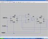
I need to have a tilt switch that goes to a flip-flop, at least that's what I think I need. What I'm looking for is a kind of switch that when I press a tactile switch or something it will turn on and then when I press it once more it will turn off. Will my proposed circuit work? Instead of the tactile switch, I'm going to have a tilt sensor. When it moves a certain way it will activate this circuit and then when It goes back to the origional position it will stay on. When It goes to that position again, it should turn off.

Thanks in Advance! ;)
 
A filp flop would work, properly configured. There are other methods, dpending on the exact application.
 
A filp flop would work, properly configured. There are other methods, dpending on the exact application.

Yeah, I need a tilt sensor for the input and at the output of the flip flop I'll have it going into this circuit which will determine whether the power is on or off. Would there be a better way to do this? How should I configure the flip-flop?
 
Well, I'm not sure what "this circuit" means. I guess it's just a microcontroller or someting, in which case, a flip flop would be ideal. It should be configured as a 1-bit counter, which means a D-type F/F, for example, would connect the Q BAR or the inverse of the Q output to the D input, and your tilt switch would connect to the clock pin. However, you're going to need to "debounce" you switch, and even a normal bebounce circuit might not work well, as the tilt might "make" and "break" many times before settling. If you used a J-K FF, then I think the J & K can just be connected to VCC or ground, and it will automatically do what you want. Either way, make sure the flop is reset at power up.

I think this might a very dicey proposition, unless you can add some sort of mechaincal hysterisis to the tilt switch.
 
Last edited:
I totally take back my earlier post. A better way to configure you flip-flop is to connect the clock pin to a clean clock signal. Then connect the Q BAR output to the D input. Then connect your switch to the FF's "enable" connector. If there is no enable, then implement this at the D input:

D = Q BAR AND SWITCH OR Q AND NOT SWITCH. (simple multiplexer) However, you'll need a FF to synchronize the switch signal to your clock first.

A J-K FF might make this a little easier.
 
Last edited:
"The Circuit" isn't a microcontroller. I just need it to power this 555 timer circuit I have. Instead of having the mechanical switches where they lock in place, I need one where I can push it and it will turn on, and then I can push it once more to power it off. How do the radios and computers do it? I mean they have a power switch just like what I need.
 
I could, but I don't have any digital symbol graphics. My mouse drawn logic is hideous. I'll try to find a free graphics program, but I don't know if that'll do you any good, as you pobably need an answer now.
 
Last edited:
Go to Linear Technologies hompage and download the "LT Spice" it's relatively simple to use.
 
Here is the best idea. It takes two FF's. Make sure you double-check my logic before building, as I did this in my head. The gates should be 2-input types.

Now I remember why I don't do logic in LTSpice. I can't get 2-input logic.
 

Attachments

  • FF&TILT.JPG
    FF&TILT.JPG
    99.3 KB · Views: 1,121
Last edited:
Any method that holds the CLR pin at the reset level while the powe supplis stablize will work. Use the device data sheet for more info. (whatever FF device you are going to use)
 
Last edited:
So here is the theory of operation:

I have a tilt switch and when It moves a certain way it will conduct but only for a moment. It will then go back to its original position. During the time it conducted, it would have activated the analog switch (or flip flop) and turned on my 555 circuit. Even though the tilt switch isn't conducting anymore, the circuit is on. However, if I move the tilt switch again so it conducts for a short period and then back to its origional position, it will turn the circuit off.

So if I use that analog switch I suggested it will do that?
 

Attachments

  • FlipFlopSwitchCompleteOperation.JPG
    FlipFlopSwitchCompleteOperation.JPG
    16.9 KB · Views: 251
I'd like to have just a small device that would do the dirty work, not a bunch of discrete ICs or components. I suppose I'll use the flip-flop?
 
In engineering, you don't necessarily get what you would like to have. To do it right, you'll have to use components properly.

PS: If you use a 556, you can configure one timer as a simple flip-flop. I can't provide a drawaing... just look it up. You'll probably still need some logic, however.

Guess you could always use a microcontroller. :D
 
Last edited:
Why the gates??

if I am reading this right
pus on (tilt switch is closed "on")
push again (tilt switch off (open")
I think just a simple divide by two D flip flop??
I was playing with similar just last week for a model train crossing.
when the 555 timer is on is it a monostable or astable??
as for debounce I think just a capacitor/resistor/transistor might do the deed??
a schmit-nand gate would be better.
 
Status
Not open for further replies.

Latest threads

New Articles From Microcontroller Tips

Back
Top