Continue to Site

Welcome to our site!

Electro Tech is an online community (with over 170,000 members) who enjoy talking about and building electronic circuits, projects and gadgets. To participate you need to register. Registration is free. Click here to register now.

  • Welcome to our site! Electro Tech is an online community (with over 170,000 members) who enjoy talking about and building electronic circuits, projects and gadgets. To participate you need to register. Registration is free. Click here to register now.

Flip Flop - LM555

Status
Not open for further replies.
Can you send me the model or what ever I need to make my sw work, I matched yours as exactly as I could, but couldn't get the switching action.
Thanks
Kinarfi

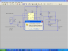
I did in the previous post. The .asc file I posted should run if you open it with LTSpice. Get mine running, and then change it to add more stuff.

ps, I just tried it, and it simulated fine...
 
Last edited:
Yes, your sim works fine, the place mine was failing was at the switch, after analyzing yours, I notice the pulses of the voltage source for the switch needs a negative value, after fixing that, mine works fine also. Would you please send your .Model PushButton SW() or switch (SW) model and what does .IC V(C) = 11 do?
Thanks for the help,
Kinarfi
 
The SW model is on the .asc file I posted (no other files are needed) . The LTSpice switch is open if the control voltage is negative, and is closed if the control voltage is positive.
The switch has a bunch of defaults, which are in the LTSpice help file; Ron = 1 Ohm, etc. The .MODEL statement would be more complicated if you want to override any of the defaults.

.IC V(C) = 11 sets the voltage at node C to 11V at the start of the simulation. Try it without, and you will see what it does.
 

Attachments

  • switch.png
    switch.png
    62.3 KB · Views: 181
Last edited:
Thanks, Much appreciated!! Here's what my final is, at the moment, I'm always changing things.
Kinarfi
 

Attachments

  • Divide by Two.png
    Divide by Two.png
    10.7 KB · Views: 218
  • Divide By Two.asc
    3.3 KB · Views: 184
Mike, after reading your last post, which didn't say what I wanted it to, I started digging and found that one of MY problems was syntax errors and that you were correct, of course, every thing I needed was in your .asc.
When I ran MY previous .asc, I would get first attachment, then the second, and after my learning and correcting, my .asc runs like it should and I can change values around to see what happens.Thanks again for help.
Kinarfi
 

Attachments

  • untitled1.png
    untitled1.png
    51.6 KB · Views: 185
  • untitled2.png
    untitled2.png
    44.4 KB · Views: 164
  • untitled.PNG
    untitled.PNG
    20.3 KB · Views: 184
Last edited:
Thanks, Much appreciated!! Here's what my final is, at the moment, I'm always changing things.
Kinarfi

This design works great on the bench with FETs driving ≈ 2 amp lights, driven by a Lamda power supply, but in the vehicle, it tends to lock up and not switch, likes to to stay on high beam which pulls ≈10 amps.
It's a great circuit, one I've wanted for a long time, but for my camper, I have gone with this design, sweet and simple.
Thanks for the help,
Kinarfi
 

Attachments

  • 47502d1288157050-flip-flop-lm555-divide-two.png
    47502d1288157050-flip-flop-lm555-divide-two.png
    10.7 KB · Views: 192
  • Camper Dimmer Swith.PNG
    Camper Dimmer Swith.PNG
    8.9 KB · Views: 503
Your MOSFETs are good for 5 amps Id max. Your low beams draw 6 amps and your brights need 10. Something's gotta give.
Vgs max is 12v but they're running at 14.4. Something's gotta give.

There is no protection from 14.4v bus transients.

I know its not as much fun, but if you ended up with a maintained contact switch, why didn't you just go with a $5 automotive 30/20 amp SPDT relay that is bulletproof and proven to last? Or one of these with the original push button plan but more expensive:

**broken link removed**
 
Last edited:
OOPs, when I simmed this, the sim didn't have a IRF4905 55V-74A FET so I used the first International Rectifier on the list. I mounted them on a nice heat sink out of a computer server power supply, and I had the FETs on hand and they only cost $1.58 each. Don't expect any problems from them.
One question though, for every body, why does the IRF4905 come in a seal envelope with a humidity indicator and that moisture absorbing gel and baking instructions? Am I supposed to remove them periodically and bake them.
Kinarfi
 
Last edited:
Next time some idgit asks if a 555 will work as flip flop, tell him to just go buy a d flip flop for 30 cents and to not worry about it. That's what I should have done.
Kinarfi
 
Last edited:
Status
Not open for further replies.

Latest threads

New Articles From Microcontroller Tips

Back
Top