Continue to Site

Welcome to our site!

Electro Tech is an online community (with over 170,000 members) who enjoy talking about and building electronic circuits, projects and gadgets. To participate you need to register. Registration is free. Click here to register now.

  • Welcome to our site! Electro Tech is an online community (with over 170,000 members) who enjoy talking about and building electronic circuits, projects and gadgets. To participate you need to register. Registration is free. Click here to register now.

flashing LED

Status
Not open for further replies.

1997 GA16DE

New Member
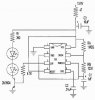
I just added a car alarm to my car and I mounted 2 blue LEDs on my front pillars that flash when it's active. I was hoping to tap off of the existing LED, but there's just not enough current to power all 3. I decided to jus tap a 12V source and make my own LM3909 or 555 flasher.

I tried searching for some schematics for this, but I only came up with 1.5V and 5V circuits. I need something that can work on a 12-14V system. Both LEDs will run around 20mA and I want both to flash at the same time (prolly run in series...BTW, each one is on the opposite side of my car).

Thanks.
 
The 1.5V and 5V circuits would do! A 555 timer can be run off 12V and with a 1k resistor in series with the LED you can use 12V for that too. If you want them to flash at the same time, just connect them in parallel across the O/P and the Ground of the circuit, with the resistors as well. To find out what size resistor to use for the 555, I would have a look at the datasheet. There's quite alot of information about 555 timers on the net.

I've just looked at the data sheet and the supply current is 15mA (max). So at 12V you'd have to use an 800R resistor, but I'd use a 1k just to be on the safe side. The IC would still function. You can find the datasheet here: https://www.hobby-elec.com/pdf/e_lm555.pdf

I hope this was of some help to you.
 
canadianpoet2012 said:
If you want them to flash at the same time, just connect them in parallel across the O/P and the Ground of the circuit, with the resistors as well.

If you want the LEDs to flash in unison, I would put them in series and then you only need one resisror and the current is half of what it would be if they were in parallel.

Len
 
ya, @ 15mA, I'll prolly go up to a 1kohm the voltage can peak at 14V which would require 933ohm.

I'm still a bit confused how to wire up the 555 timer. What type of cap should I use to make it flash about once a second and can I give it sort of a strobe effect where it's a quick flash, rather than on-off-on-off...

If anyone can make up a schematic, I think it would make more sense to me, I know more about cars then I know about electronics.
 
This is a good schematic for 555 timers. It has a very breif explanation of the two most common types of timer circuits. As for what capacitor to use, you really need to look at the datasheet. You can find out the value for the capacitor you want, you'll also need resistors too. The timer uses a RC configuration to determine the frequency of the pulses. Strobe effect is quite possible as well. Although with an LED it would be hard to tell the difference. They are either on or off, and when they switch on or off the transient time is very very quick, (nano seconds). They are not like light bulbs in that they turn off 'slowly'!

**broken link removed**
 
Oh sorry, I missunderstood! Yes, your strobe effect is more than possible, but again you would need to study the datasheet. Time permitting I will have a go at designing a suitable circuit for you with the component values! But I am very busy at the moment!
 
This circuit should produce the oculting light that you want:
 

Attachments

  • OCULTING_LED.jpg
    OCULTING_LED.jpg
    17.5 KB · Views: 1,065
A easier solution would be to get a normal flashing LED and connect all three LED's, the two blue and the flasher in series. You would not need any resistor and all the LED's would flash in sync. If you did not want to
have the flashing LED visible, you could cover it with black electrical tape.
 
k7elp60 said:
A easier solution would be to get a normal flashing LED and connect all three LED's, the two blue and the flasher in series. You would not need any resistor and all the LED's would flash in sync. If you did not want to
have the flashing LED visible, you could cover it with black electrical tape.
Hmmm, I never thought of that. I actually had one lying around and I tried it. the flashing is the right timing, but the other LEDs don't go out all the way, they dim when the flasher is off, then brighten when the flashing LED blinks. It's not exactly what I expected, but it looks interesting, I may try that out, thanks for the idea.
 
well, looks like I'm going with K7's method. I tried out Russlk's diagram for shits n giggles and I jus ended up roasting that first 47ohm resistor. I really don't know enough about electronics to do this kinda stuff.
 
Status
Not open for further replies.

Latest threads

New Articles From Microcontroller Tips

Back
Top