Continue to Site

Welcome to our site!

Electro Tech is an online community (with over 170,000 members) who enjoy talking about and building electronic circuits, projects and gadgets. To participate you need to register. Registration is free. Click here to register now.

  • Welcome to our site! Electro Tech is an online community (with over 170,000 members) who enjoy talking about and building electronic circuits, projects and gadgets. To participate you need to register. Registration is free. Click here to register now.

Flashing LED project

Status
Not open for further replies.

dogsofwar

New Member
I need help with a very small and very easy project. Or so I think :)

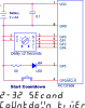
I need to build a flashing LED that will gradually lessen the time between flashes until eventually reaching the point of constant on, and at that time turn off. The time I'm aiming for is to take around 10-15 minutes to reach the off mode.

I'm not a complete newbie, as have taken several courses of electronics way back in high school. But as everything else I learned in school, isn't easy to remember these days.

I would like to keep the project small: small battery, 1 led, I'm assuming some chips may be in order, and need a reset button.

Also, if possible, and I need to have a way to either lengthen or shorten the time it take to reach its off mode. Not exact, or variable, but for example, allow it to adjust between 15 minutes and 30 minutes.
 
I'm thinking of using a ripple counter, but I'm not sure how one exactly works.

Very simple example:
Q1 (4)
Q2 (8)
Q3 (16)
Q4 (32)

Does this mean that Q1 will count 4 times, then Q2 will start counting? And once Q1 has counted to say 4, it remains high? Or does it fall back to low when it goes to the next one?
 
What ripples in a ripple counter is the carry bit. Each rising edge of the clock causes the least significant bit to change state. If it changes from a zero to a one there is no carry and the count is correct. If it changes from a one to a zero then ther is a carry into the next stage. If the next stage is a zero it becomes a one and we are done since ther is no further carry. this process continue until all stages of the counter have been updated.

In a short counter you hardly notice the delay due to the ripple. In a long counter there are many invalid intermediate states that the counter goes through before it settles down to a valid count. That is why smart designers never ever directly decode the output of a ripple counter; you shouldn't do it either.
 
Well, I'm just not sure how to design this project.

From doing some research on this, it looks like I can raise the frequency of the clock by decreasing the resistance going to it. Can I run a LED directly off of the clock? Then what would I use to gradually decrease the resistance?

Also, this project has to be as small as possible.
 
Its to simulate a bomb that counts down and detonates.

As time passes, I want the LED to flash faster, indicating that its about to blow up. Then to signal that its detonated, I want the LED to turn off.

The reason that it must flash faster as time passes, is because there is no set time, say exaclty 10minutes or 15minutes. If it flashed exactly the same rate, you would never know if the time was running out or not.

Reason that it has to be as small as possible, is that its to be used for miniature war games. Can't be using this if its got a huge battery and circuit board.

Does this help? Specific components are not required, as long as it is small and the LED works as needed.
 
This begs for a 6 pin microprocessor like the Microchip 10F200. The outputs will drive up to 25 mA, easilly enough for a typical LED. And it will run on 2V to 5.5V.

But you want a small battery. A typical LED will kill a small battery in short order. You'll need a super efficient LED, running around 1 to 2 mA, to last for any length of time. Two AAAs will give you enough voltage to run the chip and enough power to run the high efficiency LED for several minutes.
However, you'll have to write the code for this, buy a programmer to put it in the 10F200, and then solder the chip to a board with the LED, a limiting resistor and a reset switch. By the way, this does come in an 8 pin DIP package, which is large enough to put this, and the other components, on proto boards you can buy from Radio Shack.

I can't begin to concieve of a way to do this in an analog circuit without making my head hurt.

End two cents.
kenjj
 
One way to do it with out a uprocessor is to use CMOS 4000 series IC's. Use a CMOS 555 timer as the LED flasher. Use a 4060 oscillator divider to drive a 4051, 1 of 8 analog switch to switch 8 different values of resistors for the
555 timer. Have the 4th bit of the 4060 divider turn the whole thing off.
Use a 3V lithium coin cell for power, it will flash the LED's for at least 15 minutes.
If you want a circuit I think I can draw you one.
Cheers
 
BOMB BLAST LED FLASHER
THEORY OF OPERATION
When the poser is first applied all the counters in the 4060 are reset to 0 with the capacitor
connected between pins 12 and 16. This also turns on the 2N3906 transistor which applies
power to the LED.
The resistors and capacitor connected to pins 9,10, and 11 of the 4060 comprise an oscillator at
about 2Hz. This is divided by 128 and provides timing of approximately 1 minute to the analog
switch CD4051 pins ABC. Every minute a different timing resistor is selected for the 555. The
555 is used to flash the LED. The 470K is the longest flash rate. Pin 4 output has no resistor
so the LED is on steady. After the LED is on steady for about 1 minute pin 15 of the 4060
goes high and turns of the LED. After about a minute the whole cycle repeats.
 

Attachments

  • BOMBBLAST.BMP
    50.7 KB · Views: 172
It's funny, the way I'd do this is more a function of my junkbox - a 12F629 + a hexdecimal-encoded switch (plus a couple of resistors). The hex switch would give me 16 possible "bomb delays". 4 pins for the switch and 1 for the LED. Maybe one more pin for a start (reset) switch. smaller, more flexible and probably cheaper. still, it presumes uC knowledge.
 
kjennejohn said:
This begs for a 6 pin microprocessor like the Microchip 10F200. The outputs will drive up to 25 mA, easilly enough for a typical LED. And it will run on 2V to 5.5V.

I agree. Easy with a PIC. OOps LED is backwards lol.
 

Attachments

  • PIC Countdown Timer.png
    PIC Countdown Timer.png
    8.7 KB · Views: 167
yeah, that's prettymuch what I was thinking. WPUs enabled.

One problem I've had in running the 629 off of +3V is that the output drivers didn't generate enough voltage or current to drive an LED to full output. I never did get a reasonable answer from microchip on this one. I had a long discussion of this on the microchip forum and several suggested that the mos output drivers didn't saturate at 3V. I dunno, I added a transistor driver and got full output. I don't know if the 508 is different.
 
Last edited:
Status
Not open for further replies.

Latest threads

New Articles From Microcontroller Tips

Back
Top