Thats a bit simpler yet then.
")
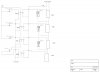
You will only need one relay, but it will have to be a bigger one, able to handle the total current of all the lights added together.
Like Duffy said, the switces will just get wired in series, meaning SW1 will supply power to SW2 and so on, down the line to the epic button.
Using double pole, single throw switches, you can make the LEDs come in in any order the switches are thrown. One pole of each will be used for the relay and the other pole for the LED.