Continue to Site

Welcome to our site!

Electro Tech is an online community (with over 170,000 members) who enjoy talking about and building electronic circuits, projects and gadgets. To participate you need to register. Registration is free. Click here to register now.

  • Welcome to our site! Electro Tech is an online community (with over 170,000 members) who enjoy talking about and building electronic circuits, projects and gadgets. To participate you need to register. Registration is free. Click here to register now.

Filter Circuit for ADC

Status
Not open for further replies.
Hello people!
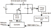
I am using a Voltage Sensor to sense dc output voltage of a DC/DC converter and then this sensed voltage is picked up by ADC for Closed loop operation.
Dc-to-dc-boost-converter-circuit-with-closed-loop-system.png


I have following doubts
  1. Since, there will be some ripple in Output Voltage, do i need some sort of filter before ADC?
  2. Will a low pass filter sufficent? If yes What should be its cut-off frequency?
  3. What qualities should I look in the op-amp or which op-amp will be sufficient if my switching frequency is 10KHz?
datasheet of the voltage sensor is also attached.
 

Attachments

  • Dc-to-dc-boost-converter-circuit-with-closed-loop-system.png
    Dc-to-dc-boost-converter-circuit-with-closed-loop-system.png
    16.8 KB · Views: 140
  • VH1K0T01_Voltage_sensor.pdf
    107 KB · Views: 148
Assuming you're after a decently smooth DC output?, then ripple should be more than low enough for the A2D - however, it's common to not have a single 'C', but to have two of them, with an inductor connecting the +ve's forming a PI filter. Also stick small value capacitors (0.01uF for example) across the two capacitors.

What's with the 'voltage sensor', and the flash ADC, doesn't your controller have ADC built in?.
 
Which method do you pick for filtering the sensor input. In real-life that is done by:

0. Software. Benefits: easier, faster, less soldering, less money for components. Downside: more programming, more understanding.
1. Hardware. Benefits: less programming, only connect the circuit, works if the MCU is damaged, needed for some special environments perhaps. Downside: more components, more soldering, more testing, higher chance of problems with the capacitors, more money.
 
I don't understand how it will be done.
I will tell you. When you want to filter a sensor through software, you have to consider the following: You will get some readings, for clarity we will take them to be from 0 to 255. During an amount of time, for clarity we will take 5sec, these readings will change.

For 5 sec you will be getting approximately the same readings, but they will be going up or down with a little, depending on what the sensor is measuring. However since there are intereferences from time to time you will not get an aproximately the same reading (125, 124, 128 for example), you will get a spike(240, 20 for example). To filter these spikes there are a lot of formulas.

This is the most common software filter applied: olympic average, it means that you take a number of readings, you sort them in increasing order, you remove the last and the first reading(that would mean the smalles and biggest) and you average the rest. In this way any spikes will be removed and you will average the (125, 124, 128). Depending on what are measuring you need to set the samples(amount of reads to Olympicaly average) and you might need to combine it with a hardware filter. Normally the hardware filter is not necessary.
 
There is much written on filters for ADC.

Noise = PWM frequency, PWM duty cycle, speed of the Diode and Transistor. If the PWM is running at 100khz then you have 100khz + (100k to 300k) + (noise at 5 to 100mhz) AND You will find that your sampling frequency adds noise. Remember if you add frequencies together you will get 4 frequencies. (F1+F2)= (F1, F2, (F1-F2), (F1+F2) SO If PWM frequency = 100k, and ADC sampling at 90k then you will see a 10khz noise that is really not there. So your error amplifier might respond to 10khz and .......

If your filter is too slow it will effect the response time of the power supply. The loop stability will be hard if the filter is set too low.

I would add a simple RC low pass filter on the input of the ADC. My guess is: at 100khz have a gain of 1/4 to 1/10. (I have done this. I don't really now the math. I think there is too many unknowns to find a simple formula.)

Soft ware averaging is going to add delay and phase shift. My supplies need fast response time.
 
I will tell you. ..
What he didn't tell you (or doesn't know) is that there is no way to filter the samples in software if they are "aliased" into the sampling passband by the ADC, due to a missing, external low-pass, anti-aliasing filter.

An anti-aliasing filter can be as simple as an RC filter (just one resistor and one capacitor) , or as complicated as a multi-pole op-amp based active filter.

How aggressive the anti-aliasing filter has to be depends on the frequency spectrum of the signal being sampled and the sampling rate of the ADC.
 
with an inductor connecting the +ve's forming a PI filter
Unless you have experience with LC filters, don't. To complicated for you. The filter might ring unless you have it heavily dampened.
A "L" on the input of the ADC might pick up energy from the main transformer/inductor and actually add more noise. Inductors coupling is a problem in high power devices.
 
Status
Not open for further replies.

Latest threads

New Articles From Microcontroller Tips

Back
Top