Continue to Site

Welcome to our site!

Electro Tech is an online community (with over 170,000 members) who enjoy talking about and building electronic circuits, projects and gadgets. To participate you need to register. Registration is free. Click here to register now.

  • Welcome to our site! Electro Tech is an online community (with over 170,000 members) who enjoy talking about and building electronic circuits, projects and gadgets. To participate you need to register. Registration is free. Click here to register now.

Feedback on Schematic

Status
Not open for further replies.

LabRat

New Member
Well now that I have my Junebug operational, I've been reviewing my next little toy. I've talked to the kids and we have plans to use one of the USB enabled devices with a bootloader to make a small device that will be "field programmable". The plan is to use up as many of the spare parts that I've been amassing in the basement.

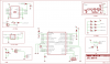
Keeping in mind that I'm more of a software hacker, I would appreciate feedback as to any obvious "gotcha's" in the following design.

Thanks
 

Attachments

  • MyBoard.PNG
    MyBoard.PNG
    44.3 KB · Views: 403
It's hard to read your schematic but from what I can make out it looks fine. The only slight changes I would make are, make the LCD contrast a preset and maybe move the tacho to a pin that can count (ccp1 or timer1/3 external clock.

Mike.
 
Is that a resonator with caps? or a crystal without caps?
Use a crystal, there will be a table of USB OK crystal speeds in the datasheet. USB has to be 96MHz (that's a PLL value)
Up your MCLR pullup to 22K or add a diode in series with the 4.7K
Your IR detector would be happier with 100ohm & a small cap 4.7uf on its VCC (Junebug schematic shows this)
Your fan may need a 1N4001 clamp diode.
Recommend you add an ICD (Junebug) connector, MCLR, RB6, RB7 will make debugging / programming MUCH easier. Swap the IR_DATA with FAN_TACH (you'll have to disconnect the fan tach to program/debug) or some other high impeadance pin.
OR GND the RW pin on the LCD, and move the FAN_TACH to TMR0 (RA4) it's a counter!
You don't need R4 (just set the PORTB pullup in software)
A ferrite bead on the USB power pin to VDD also recommended.
I remember Elektor made an automatic LCD contrast with a TL431 shunt.
 
Last edited:
LabRat said:
I would appreciate feedback as to any obvious "gotcha's" in the following design.

Are you sure your parallel LCD interface uses D0~D3 on the LCD module for data?

Most use D4~D7 instead.
 
eblc1388 said:
Are you sure your parallel LCD interface uses D0~D3 on the LCD module for data?

Most use D4~D7 instead.

hi,
As he is using the LCD R/W line, [ to test BUSY on D7, I expect] I agree with your comment.:)
 
Thanks everyone.

LCD 4..7 vs 0..3 - Good CATCH!!

Bill. The "plan" was to not require ICD as I was going to use a USB bootloader. The part will be flashed once with the bootloader, and then installed into a socket on the board. If/when I go to surface mount parts, I would include an ICD header.

I was thinking crystal resonator with caps.. saw this being done on a similar board (Usb <--> LCD thingy.. at Sparcfun I think)

I will be proto-typing the fan/clamp diode etc, so thanks for the heads up. Will trial it all before attemping to layout my board.

Will read up on the "counting" capablities.


Thanks again... everyone.
 
I would get rrid of the BJT / Base resistor combo and instead use a logic level FET and a small pull down to bleed off any gate charge. You won't have a drop across the FET (or at least not one that is 0.7V) so you won't get as much heat or waste. Secondly, those Vishay IR demodulators are very good and very sensitive. Just to make sure you don't have any noise across it, I would put a cap close to it across its power. You can always no-pop it when you spin the board but if you find you need it later and didn't plan for it, things are more difficult.
 
Thanks Crust.. heck of a good idea to plan for the extra pins. I think I will plan for the ICD header as well.. (can always leave it depopped)
 
Pommie,

What made it "hard to read" for you? Is this a physical "image" issue? or something in the way I presented the information?

(Always learning)
 
Yep you'll need a pullup or two on the I2C bus. Also many resonators are not very accurate, I've not looked at the Sparkfun USB board though.
 
Yeah.. I guess.. sort of. We have a bunch of LCD's that fit "exactly" into the opening window of a 3.5" drive opening of a 5.25" drive bay. (You know.. the plastic flange that went on the front of a 5.25" bay) We wanted to get that working, and as I have a bag of fans here, thought we could have the device PWM control the fan speed. But lo and behold, I had some I2C temp sensors, so thought to throw those on as well.. and some neat pacakges with multiple LED's. Great fun bit twiddlers everywhere.

I was aware of the USB bootloader option of the "bit whacker" and thought it would be ideal for my kids to try their hand at breaking^H^H^H^H^H^H programming these devices. Then my son asks how will he tell it what to do? So we came up with IR remote receiver as an input device. Yep.. I actually had to *PAY* for those. Everything else has been in house (basement) or sampled from the fine people at Microchip.

Pretty much the progress so far...
 
Oh.. there's also the step of trying to make a board that will fit across "behind" the LCD and mounting the LED's and IR sensor on "either side" of the LCD. Which means I would be outside the size of the "free use" area on Eagle. Just one of the many hurdles coming my way. :)
 
I've been working on a similar device. I've used a PIC with an LCD controller built in and RS485 (long range) instead of USB (short range)
I've also just got my hands on 4.096 shunt reference ICs, that'll lower the resolution but the conversion becomes dirt simple.
**broken link removed**
 
Unless you need a fancy display the LCD PICs are amazing, displays are dirt cheap.
PS that backlight will throw off any temperature sensor too close when it's on. Also run your PIC as slow as possible, else move your sensor off board.
 
You've got me thinking about the thermostat again, and TQFP PICs.
I really like this display and there is a PIC that can drive it perfectly
Nice for a moving message display and about $3 too!
**broken link removed**
 
Just an update to those who provided such valuable feedback.

1. Received and got my JuneBug working (Thank's Bill)
2. Tested the LCD on the JuneBug via Port B (thanks for the sample code)
(trim pot for contrast was missing.. after much head scratching tracked
this down and hard wired in a 1.2K resistor (for now))
3. Tested IR circuitry with JuneBug and re-worked sample SIRC code to
accept 32 bit signals from Apex controller. Updated my schematic to
match JuneBug.
4. Wired up the Fan (minus clamping diode) and found that I would need
a pull up resistor on the TACH line. Even with this resistor things were
not working properly. Turned out I have a bad fan with a blown TACH.
(Lucky for me.. I have a bag full of fans)
5. LCD drivers - no issue here. JuneBug sample code is fairly straight forward.
6. There is no item 6
7. Received my 18F2550 sample from Microchip (thanks Microchip),
Wired in my switches, led's, oscillator, and LCD's onto a proto-typing
breadboard.
8. Hooked up the JuneBug ICSP header, and ... (I know you are dying to know)
Detected and programmed the device!!


...


... nothing happened.

Ok.. that's the progress so far. I will keep you posted.
 
Last edited:
Status
Not open for further replies.

New Articles From Microcontroller Tips

Back
Top