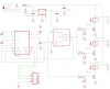
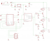
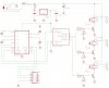
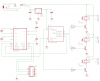
I am building a three channel relay board to power up/down my inverter, air compressor and 12V outlet panel via RS232 commands from a control panel.
It is working as drawn on a breadboard, I want some experts to look it over and provide feedback before I mill a circuit board and assemble it. A whole lot easier to change now than later!
Is it ok to drive 12V Bosch style automotive relays with a single PN100 transistor via 5V to the Base? Can a transistor switch 12V from a 5V base signal or are they intended strictly for current amplification at the same voltage level?
The relays have a coil rating of about 95ohms and draw approx 100mA and are rated to 40amps on the contacts.
Thanks,
David
")