I'm here again.. I already figured out how to employ negative feedback in my ckt. my ckt is doing well in simulation but not so good in actual testing.
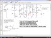
here are the notes i took:
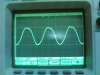
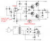
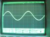
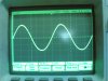
1.) cap C7 (9v to ground). when i tried to make this 1mf, the voltage in the voltage source went down. i immediately turned it off. it was about ~7V. its supposed to dampen the ripples in the source right? not only that, when i increased C7 from 100uf to 200uf, the gain at the output got a little bigger. that's why i tried to make it even fatter(1mf). can anyone tell me why is this happening?
2.) the output was REALLY DISTORTED. but after about 15 to 20 seconds, the output slightly smoothens out. what really bothers me is that when i adjusted bias resistors R13 and R14(i momentarily turn them to minimum then turn them up again) the distortion before just vanishes. i forgot to take a picture of the distorted waveform, sorry. I don't know if it was just the scope i was using though, it was semi old and i havent got the permision to use the new ones(still in the package box.)
I'm afraid that when i take this to my teacher, he wont check my workbecause of this.
3.) minor thing: the 2n2222A and 2n2907A i use are in the round metal casings. the 2n2222A looks pristine, the 2n2907 is like.... burnt... at first it was a little yellowish. now its more brown than yellow. do you think the 2n2907a is hogging most of the current? i suspect that this has something to do with the potentiometer biasing i made, sometimes the biasing just go too low, or too high.. btw, 2 burned the first 2n2907.. i tried biasing with 100k pots at that time. i dont know what happend, but the 2n2222A was still intact.
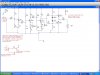
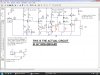
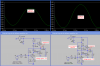
4.) In SIMULATION: if R9 is lower than R10 (e.g. R9=33kohms R10= 100Kohms), the output at the collector of Q3 distorted at the upper part. i tried bypassing R10 (i guessed that the AC impedances has something to do with the distortion, i was wrong) but it was still distorted.
5.) in SIMULATION of the ACTUAL CKT: the frequency response tells me that f>1kHz has a pretty stable gain, in reality, it has not.
i guess i should tell you the requirements:
-> 0.2Watt rms at the output (~1.8v peak)
-> i use 8ohm 0.5watt speaker
-> no distotion
-> from 25Hz to 20kHz
-> suggested use of preamp stage and voltage driver(i have no idea what the hell voltage driver means, maybe amplify the voltage to levels greater than line voltage?)
-> BJts only. no opamps/jfet/mosfet
enlightment please!!! thanks!
PS:
Your transistors have a fairly high collector-emitter current but a current that is too small in the divider that biases them. Then the transistors with low current gain will not have enough base current and temperature changes will also affect them.
pls. enlighten me about this.. all i know is that i have to compute for the thevenin equivalent of the biasing network then compute accordingly to get the wanted base voltage bias.. i dont know about the currents...
can anyone tell me where to get a more precise model of a speaker? the 8ohm resistance just can model it. thanks!!