Cry_Wolf
New Member
Hello all Respected Members,
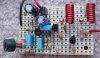
I am really fedup of wrapping wires around the proto type boards and soldering them, It becomes a mess (just like a bird's nest) and its very hard to debug if any thing goes wrong. Now I have finally decided to go for the PCB.(I have never done PCB layouts before ).
).
Now the question is which Software should I use (I expect you to say EAGLE). I have been going through some EAGLE tutorials but cannot get hands on it . I would like know some other softwares that are easy to use and are efficient for atleast single side PCB design. If you people still insist that eagle is the best so please provide me some good tutorials and hints.
Thank You
I am really fedup of wrapping wires around the proto type boards and soldering them, It becomes a mess (just like a bird's nest) and its very hard to debug if any thing goes wrong. Now I have finally decided to go for the PCB.(I have never done PCB layouts before
). Now the question is which Software should I use (I expect you to say EAGLE
). I have been going through some EAGLE tutorials but cannot get hands on it . I would like know some other softwares that are easy to use and are efficient for atleast single side PCB design. If you people still insist that eagle is the best so please provide me some good tutorials and hints.Thank You