ecaits
New Member
Dear Friends,
I am working on PIC16F877 project. I am using ADC and taking the signal from sensor and giving it to analog pin.
I am preparing the circuit in which I am considering the four point given below.
1. When sensor is short, at that time I am getting 0mV and I can declare that Sensor is fail in program.
2. When sensor is open, at that time I will get some noise from atmosphere and I will reduce it to 0mV by resistor so that I can declare it as sensor is fail.
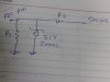
3. When accidentally, I will get over voltage (any voltage > +5) at analog pin, I will reduce it to approx 5 V by using the zener diode connected to pin and ground and by sensing the +5V at pin I can declare that sensor giving over voltage.
4.When accidentally, I will get reverse voltage (any voltage < 0 or any negative voltage) at analog pin, I will reduce it to zero voltage through zener diode and Controller will sense 0 voltage so at that case I can declare in my program that sensor is fail.
When sensor is working normally, at that time I will get voltage 0-5V and I want to give it to analog pin without any voltage drop or minimum voltage drop.
I have prepared a circuit, attached in file but it is not working properly.
Please suggest me that how can I solve it.
Thank you,
I am working on PIC16F877 project. I am using ADC and taking the signal from sensor and giving it to analog pin.
I am preparing the circuit in which I am considering the four point given below.
1. When sensor is short, at that time I am getting 0mV and I can declare that Sensor is fail in program.
2. When sensor is open, at that time I will get some noise from atmosphere and I will reduce it to 0mV by resistor so that I can declare it as sensor is fail.
3. When accidentally, I will get over voltage (any voltage > +5) at analog pin, I will reduce it to approx 5 V by using the zener diode connected to pin and ground and by sensing the +5V at pin I can declare that sensor giving over voltage.
4.When accidentally, I will get reverse voltage (any voltage < 0 or any negative voltage) at analog pin, I will reduce it to zero voltage through zener diode and Controller will sense 0 voltage so at that case I can declare in my program that sensor is fail.
When sensor is working normally, at that time I will get voltage 0-5V and I want to give it to analog pin without any voltage drop or minimum voltage drop.
I have prepared a circuit, attached in file but it is not working properly.
Please suggest me that how can I solve it.
Thank you,