Electro Tech is an online community (with over 170,000 members) who enjoy talking about and building electronic circuits, projects and gadgets. To participate you need to register. Registration is free. Click here to register now.
Welcome to our site! Electro Tech is an online community (with over 170,000 members) who enjoy talking about and building electronic circuits, projects and gadgets. To participate you need to register. Registration is free. Click here to register now.
I would think that the impedance of the capacitors in both cases would be negligible in the range of audio (500 ohms at 300 Hz). So I cannot see how the circuits would perform any differently, but something keeps nagging me that there's something about it that I'm not seeing. That's why I'm asking for opinions.
I would think that the impedance of the capacitors in both cases would be negligible in the range of audio (500 ohms at 300 Hz). So I cannot see how the circuits would perform any differently, but something keeps nagging me that there's something about it that I'm not seeing. That's why I'm asking for opinions.
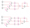
500 ohms at 300Hz is 5% of the input resistors, and will mean it's NOT a virtual earth mixer anymore. 300Hz is also nowhere near as low as audio goes, either increase the value of the capacitor, or use the preferred upper method (which would roll off the bass, but still mix correctly).
The upper circuit has a low frequency rolloff that is three times higher than the bottom circuit (the equivalent resistance seen by the upper capacitor is ≈1/3 less for a given setting of the pots). For an equivalent rolloff frequency, C1 in the upper circuit would need to be 3µF.
To answer flat5's question, the effective op amp input impedance is very low in both cases (virtual ground) because of the negative feedback.
I guess I could have been more clear by saying "in MY range of audio" rather than "in THE range of audio". The audio I'm dealing with is from a narrow band communications channel, so 300 Hz is its lower bounds. For my rough analysis I labeled the cap as zero ohms since its impedance is so low compared to everything around it.
So, if we assume that the cap is whatever value it needs to be to effectively become an AC short at the frequencies used, do you see any difference in the way the 2 circuits will perform?
If the Z at the right side of the cap (op-amp input) is the same in both circuits why would the low freq. roll off be different?
I don't see why the cap loading (Z) on the left side (cap input) matters.
Lets put it this way, if you have all the same value caps and the 0db point
occurs at 2kHz with three caps, when you short out the left side of
the caps to each other you dont change the frequency response at all,
so the 0db point still occurs at 2kHz. This happens because once the
three caps are shorted they equal three times the original value of one
cap.
If you then decrease the value of that cap (three times higher than one)
to one third of its value you of course raise the 0db point by 3 times its
original frequency, in this case it would be 6kHz.
But you had said that the cap value wont affect the frequency of operation,
so that voids the above argument so you wont see any difference as long
as the caps lowered to 1/3 of their original value dont affect operation
either.
In other words, if you operate at 300Hz and you use 10uf caps i doubt you
will ever see a difference. If you change to 100pf caps you will.
Are you implying that resistance is irrelevant to AC?
The relevance is in the different time constants (12.5k*1uF vs 4.17k*1uF). This is the same point made by others (including you, I believe). I was just illustrating it for the benefit of those who didn't see the difference, e.g. flat5.
I see the difference. My question was:
If the Z on the output side of the capacitor is the same for both circuits (op-amp input) will the freq. response be the same?
You imply no but I have trouble seeing that. If the Z is very high at the op-amp what difference does the time constant really make except for some phase difference?
The impedance at the inverting input is so low that you can assume it is zero. This is true because of feedback. It has nothing to do with the input impedance of the op amp.
I see the difference. My question was:
If the Z on the output side of the capacitor is the same for both circuits (op-amp input) will the freq. response be the same?
You imply no but I have trouble seeing that. If the Z is very high at the op-amp what difference does the time constant really make except for some phase difference?
I've mentioned a couple of times 'virtual earth mixer', which is what it is (or should be), the feedback round the opamp makes the inverting input have no signal on it at all (virtually at earth potential). This is why there's no interaction between the different inputs as they join at that point. By adding too small a capacitor at that point, it's no longer mixing at a virtual earth point, and you will get interaction at lower frequencies.
If it's any help?, no decent quality mixer would do it that way, but some really cheap crappy ones might stoop that low to save a little money.
I'm guessing you still don't understand why the impedance at the summing node (inverting input) is zero. When I first was learning op amps almost 50 years ago, there was not a lot of literature available on the subject. For me, understanding the concept of virtual ground (earth) was the key to the whole puzzle. After that, everything fell into place.
I've mentioned a couple of times 'virtual earth mixer', which is what it is (or should be), the feedback round the opamp makes the inverting input have no signal on it at all (virtually at earth potential)
Not to confuse the issue and, perhaps this is obvious, but there is actually a very small signal at the inverting virtual ground input which equals the output voltage swing divided by the open loop gain of the op amp. Since the typical open loop gain is over a 100k for most op amps, this voltage is a fraction of a mV, thus, for most practical purposes, the virtual ground has a negligible or "no" signal and its apparent impedance is a fraction of an ohm.
Well it does confuse the issue (for me)
I admit the "virtual ground" at the op-amp input is a mystery to me.
I know it is related to the negative feedback etc. and (for me) a lot of math but what I have trouble with is even if we are feeding a bjt common emitter stage, if the cap is large enough,
whatever is on the input side, impedance wize, it's the output side of the cap that will determine if the circuits will behave differently.
Do you follow me? Am I wrong?
This site uses cookies to help personalise content, tailor your experience and to keep you logged in if you register.
By continuing to use this site, you are consenting to our use of cookies.


")