Hye Audioguru,
I had build a compandor circuit to help me understand in it concept.However ,i am still not getting into compandor.I building this circuit last week.**broken link removed**
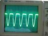
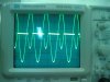
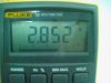
As we can see at the web,it said the threshold is 1 V.But as i measured,the threshold is about 3.78 V rms. As a result, i am getting this kind of graph on my scope which i dont really know why.
I had build a compandor circuit to help me understand in it concept.However ,i am still not getting into compandor.I building this circuit last week.**broken link removed**
As we can see at the web,it said the threshold is 1 V.But as i measured,the threshold is about 3.78 V rms. As a result, i am getting this kind of graph on my scope which i dont really know why.