Continue to Site

Welcome to our site!

Electro Tech is an online community (with over 170,000 members) who enjoy talking about and building electronic circuits, projects and gadgets. To participate you need to register. Registration is free. Click here to register now.

  • Welcome to our site! Electro Tech is an online community (with over 170,000 members) who enjoy talking about and building electronic circuits, projects and gadgets. To participate you need to register. Registration is free. Click here to register now.

encoder/decoder Ir

Status
Not open for further replies.

arivel

Member
Hello . I'd like to ask you some questions please.
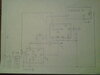
I have a problem with the Ir / Rf encoder / decoder ICs.
I only know the chip 145026/145027 no longer in production, then
holtek HT12E / HT12D, I don't know if others exist.
i would like to know if all encoders / decoders work like these two. Is there an online guide describing the existing encoders / decoders and types? .
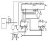
I have to use the infrared mode, with a pulsate I have to transmit the high state - low state sequence to the other side. I don't know how long the high state and low state must last respectively on the D inputs and consequently the negative pulse on the TE input because I can't get it from the datasheet. I don't know what to use to control the encoder inputs, I don't want to use anything that is to be programmed.
what is usually used to control the encoders? is there a dedicated chip to control the encoder?
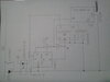
 
Pretty well everything uses microcontrollers, both to encode and decode the IR/RF - the hardware chips were pretty naff anyway, and often greatly misused as people didn't understand what they were actually for (particularly the Holtek ones).

But if you want simple remote control chips, try the PT2262/2272
 
no thanks i don't want to use a microcontroller or anything else to program. I need something that controls the encoder inputs. to simplify the control circuit it would take an encoder, if any, which returns me a signal when it has finished transmitting. in this way maybe I can do without making a timed circuit. even better if it doesn't have the TE function but maybe that's too much to ask.
 
Your actual requirements are pretty vague - so I've no idea exactly what you want - perhaps you might like to tell us?.

But the PT2262/2272 are similar to the HT12E/D in that they are for making a remote control, like you'd get on a TV.
 
a pattern is worth more than words
 

Attachments

  • forum electro-tech-online.jpg
    forum electro-tech-online.jpg
    79.5 KB · Views: 199
I'm thinking about a circuit but I need some support. I have to bring the VCC power to the flip flop and at the same time, using the same track, activate the SET input of the flip flop. what can you use? I guess it takes a slight delay between power and input. I thought of a chain of buffers on the input.
 
It sounds like you want the power up default state of the FF to be set (Q output high)

This can be easily done with a Resistor-Capacitor network connected to the set input pin. But the configuration depends on what FF you are using.

What's the part number of your flip-flop?
 
this simplified scheme is what I thought. everything is powered by stylus batteries.
an SCR in series with a normally closed OPTOmos (lcb717).
flip flop A is an SR, the other flip flop B clocked on the falling edge.
scr and optomos have the task of turning the circuit on and off, to use it only when needed. the reasons are two, to consume less energy and to obtain the repeat function when the button is pressed.
What do you think ?
 

Attachments

  • forum electro tech.jpg
    forum electro tech.jpg
    1 MB · Views: 199
this simplified scheme is what I thought. everything is powered by stylus batteries.
an SCR in series with a normally closed OPTOmos (lcb717).
flip flop A is an SR, the other flip flop B clocked on the falling edge.
scr and optomos have the task of turning the circuit on and off, to use it only when needed. the reasons are two, to consume less energy and to obtain the repeat function when the button is pressed.
What do you think ?
- What are "stylus batteries?"
- You have the capacitor that I mentioned on the S pin of flip flop A, but you need a resistor to ground on that pin to pull it low after power on. The C you've got on the R pin of flip flop B is wrong. What is it's purpose?
- What is the purpose of the SCR?
- What is the operating voltage of the circuit?
- What are the spec's of the encoder? Please post a link to it's datasheet.

When drawing a schematic, always put reference designators on all parts. It's a lot easier to comment if there are part numbers.
Also, clearly show the function of all pins on all components. The input and output of the LCB717 are not clear.
 
I answer the questions in the right order.
AA battery. two or three, I don't know yet.
.
the resistor on pin S of flip flop A (any SR flip flop) is present on the drawing maybe if you download the image on the PC you will see.
the capacitor on pin R of flip flop B (74HC112).
it has the function of supplying a negative impulse to obtain the reset.
the purpose of the SCR together with the OPTOMOS (LCB717)
there are two: operate the circuit only when needed to make the AA batteries last a long time.
achieve the repeat effect when pressing and holding the button contact.
the operating voltage depends on the voltage drop of the SCR and optomos, at least it is at least 1.2 volts, so I will probably have to use three AA batteries.
I have not yet chosen which IR encoder to use but the design was made based on HT12E.
which is what I know more than others.
tell me if it is still necessary to redo the drawing.
 
Pommie

I hate the greyish type instead of black. Saving "ink", I guess.

I also hate nothing happening on text boxes anymore. It coud say"Enter a URL or search with Google". You click on it and it's still there untill you type someting. When I click, I expect "something" to happen.
 
I just bought something that uses the HT12* chips. It wasn't clear, but I think you can transmit more than one bit. e.g a 3.

The IR to RF mode chip was discontinued. I found a breakout board for the HT chip but maybe available from India.

I have an IR to RF repeater and I'm not sure what it uses.

There are some RF chips that can actually send low speed serial data.

There is a design here: https://www.homemade-circuits.com/ir-remote-control-range-extender-circuit/

The 12D and 12E chips are available from here: https://www.utsource.net My goto place.
 
Hi.
this is the photo my mobile phone takes, I can't do more.
I have some questions.
1) I used the simplest of oscillators, port 40106 resistor and capacitor.
what other oscillator can you use that has the maximum stability characteristic?
2) as an alternative to OPTOmos lcb717 is it possible to use the Analog Switches?. For example this? :
keep in mind that when the circuit is off its input is floating.
3) on flip flop A:
is it preferable to use the SET input or the J input?
 
Status
Not open for further replies.

Latest threads

New Articles From Microcontroller Tips

Back
Top