UTMonkey
Member
Hi All,
I do more tinkering with microcontrollers than anything else, but now and again I like to brush up on the analog stuff and if anything just try to understand the underlying component which makes digital electonics possible - the Transistor.
This time I am looking at an Emitter Follower circuit, I am referring to an example from the "Art of Electronics".
The goal: make Ve =7.5, Ie = 1mA from a supply of 15v.
Now here are the steps that the source material suggests:-
1. Choose Ve. For the largest possible symmetrical swing without clipping, Ve = half of Vcc or 7.5v
2. Choose Re. if Ie is to 1mA then Re = 7.5v / 0.001 (1mA) = 7.5k
3. Choose the divider. Vb = Ve+0.6 = 8.1v. the ratio there for is 1.17 (8.1 /6.9). The preceeding loading criterion requires that the parallel resistance of the resistors be about 75k (1/10 7.5k times hFe) - suitable values are 130k and 150k
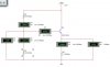
Now take a look at the "what the book suggests" attachment. The first thing that strikes me is that using the values supplied:-
1. The PD output is 7.399v when I was expecting 8.1v
2. The Ve is 6.775v which isn't 7.5V
3. Ie 90uA which is a little shy of 1mA.
Now, thanks to the great help you guys gave me in previous posts I thought I would see if I could correct this. Here's what I did:-
Taking previous steps 1 and 2 as read.
3. PD resistance = 150k = 15 / ((Ie / hFE) * 10)
4. Top resistor = 69k = 6.9v / 100uA
5. Bottom resistor = 90k = 8.1v / 90uA (10uA flowing into base)
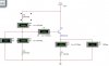
Now take a look at the "This looks better" attachment.
1. The potential divider is a couple of 10ths of a millvolt shy of 8.1v
2. The Ve is almost 7.5v
3. Ie is almost 1mA.
Now please don't misunderstand me, the book I have quoted is by far the best electronics source I have, but it suffers from what the other material I have read does - the examples just don't appear to work.
Have I misunderstood the "value" of this particular example?
Best Wishes
Mark
I do more tinkering with microcontrollers than anything else, but now and again I like to brush up on the analog stuff and if anything just try to understand the underlying component which makes digital electonics possible - the Transistor.
This time I am looking at an Emitter Follower circuit, I am referring to an example from the "Art of Electronics".
The goal: make Ve =7.5, Ie = 1mA from a supply of 15v.
Now here are the steps that the source material suggests:-
1. Choose Ve. For the largest possible symmetrical swing without clipping, Ve = half of Vcc or 7.5v
2. Choose Re. if Ie is to 1mA then Re = 7.5v / 0.001 (1mA) = 7.5k
3. Choose the divider. Vb = Ve+0.6 = 8.1v. the ratio there for is 1.17 (8.1 /6.9). The preceeding loading criterion requires that the parallel resistance of the resistors be about 75k (1/10 7.5k times hFe) - suitable values are 130k and 150k
Now take a look at the "what the book suggests" attachment. The first thing that strikes me is that using the values supplied:-
1. The PD output is 7.399v when I was expecting 8.1v
2. The Ve is 6.775v which isn't 7.5V
3. Ie 90uA which is a little shy of 1mA.
Now, thanks to the great help you guys gave me in previous posts I thought I would see if I could correct this. Here's what I did:-
Taking previous steps 1 and 2 as read.
3. PD resistance = 150k = 15 / ((Ie / hFE) * 10)
4. Top resistor = 69k = 6.9v / 100uA
5. Bottom resistor = 90k = 8.1v / 90uA (10uA flowing into base)
Now take a look at the "This looks better" attachment.
1. The potential divider is a couple of 10ths of a millvolt shy of 8.1v
2. The Ve is almost 7.5v
3. Ie is almost 1mA.
Now please don't misunderstand me, the book I have quoted is by far the best electronics source I have, but it suffers from what the other material I have read does - the examples just don't appear to work.
Have I misunderstood the "value" of this particular example?
Best Wishes
Mark