Continue to Site

Welcome to our site!

Electro Tech is an online community (with over 170,000 members) who enjoy talking about and building electronic circuits, projects and gadgets. To participate you need to register. Registration is free. Click here to register now.

  • Welcome to our site! Electro Tech is an online community (with over 170,000 members) who enjoy talking about and building electronic circuits, projects and gadgets. To participate you need to register. Registration is free. Click here to register now.

Emergency/Mini Light Bar (555 Timers,5mm LEDs 3W LEDs)

Status
Not open for further replies.

Codyf1113

New Member
Hello my name is cody this is my first time posting here on this web site.

I need a second opinion on everything I've got drawn up here so I don't go off and blow up all of my parts when I test all of it out.

I've been trying make a mini light bar to be used on my vehicle for awhile now. Using bunch of 555 timers and 5mm leds along with 3watt leds you would find off Ebay. I have a good understanding of all the parts I'm using. But I'm sure there is a mistake or something not right in my circuit. I have tested few parts of the circuit on a test board but not the whole thing all together (No Room)


Photos below are of the schematics, printed circuit board, other
 

Attachments

  • pic.png
    pic.png
    89.8 KB · Views: 270
  • mini light barlayout16.png
    mini light barlayout16.png
    220.5 KB · Views: 278
  • pcbfor555timerminlightbar.png
    pcbfor555timerminlightbar.png
    42.1 KB · Views: 259
  • pcbfor555timerminlightbarwithdrawings.png
    pcbfor555timerminlightbarwithdrawings.png
    104.7 KB · Views: 252
Welcome to ETO!
In barlayout16 half of your LEDs are reverse biased :(.
 
I recommend you find a mosfet with a lower rds. With the IRF510 you will have up to 1.4V drop across the source to drain, causing less voltage to the LED's and some heat loss.
 
Thank you

Sorry about the error in the photo mini light barlayout16.
I didn't notice I had the symbol for the LEDs drawn backwards >.< they not supposed to be.
All of the 180 ohm resistors are going to the cathode of the LEDs.

Other than the backward LEDs and the rds/mosfet. Anything else that is wrong with the circuit?
I'm going to few stores today. Is there and mosfets you know of that I should keep an eye open for?
 

Attachments

  • Edit2-17-2015mini light barlayout16.png
    Edit2-17-2015mini light barlayout16.png
    177 KB · Views: 235
The LEDs are not simple incandescent light bulbs. They will have a range of forward voltages so some will have too much current, be very bright and will burn out soon, and other will be look dim.
How will you cool the LEDs and resistors?

Why do the timers blink the LEDs on and off all the time? Are you pretending to be an ambulance or a fire truck?
 
I haven't had the chance to run all the LEDs together so I don't know how hot they will get. There isn't enough room for me to do that with my solderless breadboards. I only have had the room to test 90 of these LEDs (3x series 30x in parallel. Parallel broke up in to 2x 15 for two 555 Timers.) The LEDs them self didn't get hot but cool. The resistors didn't get hot at all. Cold to the touch. The resistors were 1/2w flameproof type.

Tested the 3w leds.
They got hot' so did the resistors. I plan on removing them from the star heat sinks they came on and putting them on to something more better. The resistors were 1w upgraded 5w resistors same type of the 1/2w I said above.

Also I'm not pretending I am part of the fire department. Allowed to display blue lights while responding to a call in a pov. Traffic issues are getting more bad and I'm not able to get up on scenes. The lights are not a free ticket to pass everyone or speed, but to ask to pass.
I also been having a lot of issues with police at vehicle accident I'm called too. Always waving their arms like crazy yelling at me to stop or turn around.
I just don't have the money to go out and buy some high price light..also where the fun in buying one when you can make it?
 
Last edited:
You dont have to remove the power leds from the star heat sinks.
Fix the stars to a bigger heat sink.
Use thermal compound between star and heat sink
 
Last edited:
To run your Star LEDs at 3W , you will need a bigger heatsink and pulse them for lower duty cycle then 1A is possible.

I have hundreds of Aluminum clad circuit boards with 18x 3W LEDs per board. I use them for all kinds of custom Luminaires inside and out.
There are many versions but the full board runs off 24V or 36V with external -DC-DC regulators.
I cut them into strips when I don't need a full board and run them off multiples of 3V for series operation up to 3.6V per LED and routinely run parallel/series arrays without any need for series R's by knowing the ESR and tolerance variations of all components in the system including the power source, thus I can prevent thermal runaway. All of mine are very consistent and have an ESR of around 1 W-Ω per LED meaning 1/3Ω at 3W or 1Ω at 1 Watt. or 10Ω at 1/10 Watt per LED in series. Lower W-Ω is better quality (but never spec'd.)

I can show you how to get more bang for the buck using MOSFET switches and use PTC"s for OCP protection for certain applications that may have a surge in voltage, but I usually run without PTC's.
You can run them off 1A at 25% duty cycle for an average current of 250mA and get far better results.
You can alternate arrays of LEDs and thus achieve constant current for some advantages and also lower temperatures.
However design of PTC thermal time constant must be carefully selected and you may elect for a precision 100mΩ current limiter with variable MOSFET gate regulation. ( or an Ultra-low LDO)

Most likely your vehicle is always running at 14.2 +/-0.2 when you want the light ON at full brightness and who cares if it dims to 50% at a low idle near 13V for example. It will still be ON at 12V.

You can therefore run 4 LED's in series with a 0.5 to 1A PTC in series. The PTC will heat up faster than the LEDs which have the benefit of a heatsink. It will regulate the current at a PTC junction temp of around 85'C . I suggest parallel PTC's like 200mA to select your desired maximum LED current and thus LED junction temperature. I would suggest the same 85'C for the LED's max. Tj.

I sell LED's in my retirement now after 35yrs of bleeding edge R&D & Mfg, and a lot more details are required to perfect what you are doing.

You can use old surplus CPU heat sinks for passive cooling in high density boards with free air assistance.

BTW, I assume you always carry written authorization from your local Fire Chief to use this vehicle flasher on your POV as a volunteer fire-fighter or medic only in real emergencies.

Although I use LEDs to avoid glare and illuminate the yard , closets and garden, you want to produce flashing glare to catch attention.

I can show some examples of 12~15V arrays of 4LED and get details on your LED of choice.

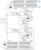
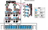
Below powered by 19V 65W laptop charger, that I modified to variable 0~24V using a custom array of 6S6P with some Amber LEDs added.
My wife wanted it brighter than direct Sunlight.
3907738400_1424450831.jpg


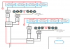
Below, for example these I made using paper lanterns ( plastic coated) with 4 LEDs cut from large board into 2"x2" square,
These are running at you might call DIM at 12.0V DC regulated brick drawing less than 2A total for 20 LEDs. If I ran at full power they would be as bright as an Ambulence Light, which is what they were designed for.

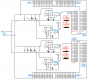
4 LEDs in series Rs=0. and 5 Lamps in parallel or 4S5P array and boards running cold under/inside shade, Wired with 30 AWG magnet wire inside to 18AWG speaker wire along eaves soffit is convenient and also prevents thermal runaway with 50~100mΩ added ESR.
7264838100_1424451909.jpg
 
I do have written authorization from my chief. I really appreciate all of the information you gave me Tony. I really like to look in to this stuff you were talking about with the mosfets and PTC's. What I have now has had me at a stand still for last few months. I kinda understand what you're telling me but again not really. I have problems reading and spelling. I'm better off looking at photos and schematics.
 
Ive used arctic silver before (for CPU's and LEDs), a little goes a very long way. You dont want to use globs of it, use a old credit card (or gift card, or card stock) to thin it around. Ive also used the cheap "knock off" brand from Ebay with good results.

How do you plan on waterproofing them? I assume they will be outside on the top of your vehicle.
 
Status
Not open for further replies.

Latest threads

New Articles From Microcontroller Tips

Back
Top