Continue to Site

Welcome to our site!

Electro Tech is an online community (with over 170,000 members) who enjoy talking about and building electronic circuits, projects and gadgets. To participate you need to register. Registration is free. Click here to register now.

  • Welcome to our site! Electro Tech is an online community (with over 170,000 members) who enjoy talking about and building electronic circuits, projects and gadgets. To participate you need to register. Registration is free. Click here to register now.

Emergency Lamp Circuit problem

Status
Not open for further replies.

lloydi12345

Member
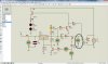
Hi I am trying to build an Emergency Lamp and got this schematic from the web.

**broken link removed**

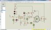
The problem is I think the zener diode is not producing enough current on its breakdown state to turn on the transistor. I tried removing the resistor R2 but still won't work. Can you help me how to make this work?
 

Attachments

  • AutomaticEmergencyLight_thumb1.gif
    AutomaticEmergencyLight_thumb1.gif
    32 KB · Views: 2,082
Hi

What website did you get this "design" from??

As far as I can see, T2 will never be able to turn on.
And T1 is not necessary.

Somebody threw bits and pieces of knowledge together and came up with this abortion of a design.

Regards,
tvtech
 
Hello there,

LOL tvtech :)

lloydi:

It looks to me that this circuit handles several functions.
1. It charges the battery, regulates the output so the battery doesnt overcharge.
2. It keeps the LEDs off until the input power goes away, then turns them on.

There are three somewhat questionable parts in this design...

First, the zener looks like the voltage selection might be too high. depending on the tolerance of the zener it may not regulate the output voltage because the drop is too high so it never conducts. This might work as long as the zener is the right voltage though.

Seond, R16 might be too large to allow the battery to charge properly.

Third, T2 may have to be a higher current transistor or Darlington if the LEDs combined current draw is significant. There's no current rating for the LEDs so it is hard to tell. And when T2 is a single transistor we'd have to see if R15 is low enough to turn it on properly.

Note that the transistor T1 will never turn on if the battery does not charge, and that could be part of the problem because of R16.

We'd also have to check the operation during a brownout with various input voltages to make sure the transistor T2 does not overheat.

So the circuit could work with a few modifications.
 
What website did you get this "design" from??
It's probably a 'destructibles' :D
 
Hi Alec and MrAL

To fix the circuit and make it work properly would be to redesign everything.

As you know Alec, lots of this floating around the Net. Heck I miss the days of Practical Electronics and all.

Regards Guys,
tvtech

And I almost forgot the OP request for help. Sorry lloydi12345. I cannot help you.
 
Last edited:
Hi again,


yes it is a bit of a strange circuit, and IC1 can probably be replaced with a transistor.

But as is, R15 may have to be lowered in value because the min gain of the BD140 is spec'd quite low, and i see now that the LEDs are probably EACH being driven at around 50ma, so that's 600ma collector current roughly. In addition to that, a resistor across the input of the LM317 is a good idea too to make sure T2 turns on fully.

With R16 a lower value and VR1 adjusted all the way up, the 6v, 4.5AHr battery might charge OK. The zener will prevent overcharging if it is sized right, but then again i would not want my battery charging all the time as many of these lights (including commercial units) do. The battery dries up.

So what's the best way to do this then?

Well, we have on the one hand the fact that we need to charge the battery with a decent amount of current to get it to charge all the way up to the max voltage, but then we need a lower voltage set point when it is time to float charge (ie keep it on standby). So we cant get away without a two stage charger i think.

Stage 1 would be charging at say 400ma until it reaches the top voltage limit of the battery like with a set point of around 7.2 volts, and then for Stage 2 lower the voltage set point to around 6.9v for the long term float charge.
This would take some sort of memory cell to acknowledge that the cell voltage had reached the max so from then on we want to only charge at the float charge level. A memory cell could be made from two small transistors or an op amp (of course a Flip Flop could be used but who wants to add that to this circuit).
 
Oh dear. I am going to be drawn into this. I tried to distance myself and it did not work :p

Firstly, the LM317T is bang on for the job.

Secondly, I believe the 10mm LEDS are just that. 10mm white LEDS that use only 20mA per LED. Total of 12x20Ma= 140Ma. Still good. No need for a BD of any sort. A little BC 337 can handle that for ever when saturated.

You see what is happening here once again. We are complicating simple things.

Just because we are bored :) And also dealing with a circuit that is a non- starter anyway. Common guys. Don't do this to me.

Regards,
tvtech
 
Last edited:
Oh dear. I am going to be drawn into this. I tried to distance myself and it did not work :p

Firstly, the LM317T is bang on for the job.

Secondly, I believe the 10mm LEDS are just that. 10mm white LEDS that use only 20mA per LED. Total of 12x20Ma= 140Ma. Still good. No need for a BD of any sort. A little BC 337 can handle that for ever when saturated.

You see what is happening here once again. We are complicating simple things.

Just because we are bored :) And also dealing with a circuit that is a non- starter anyway. Common guys. Don't do this to me.

Regards,
tvtech


Hi again,

Yup you're stuck now :)

First, the LM317 isnt doing much because the zener takes over, unless the zener is there just for protection in case the LM317 fails, but then if the LM317 fails then the zener wont help regulate anyway because it uses the LM317 to regulate too, thus the LM317 is barely doing anything. It makes the charge current a little more constant with a given battery voltage, but who needs that because the battery voltage varies anyway.

Second, when the battery is charged it can reach more than 7 volts. With 3v LEDs that leaves 4 volts, and the series resistors are 100 ohms, so 4/100=40ma each LED, and 40ma each times 12 is 480ma total through the transistor. Not a real lot, but i'd want a decent transistor there. Maybe smaller would work though it's up to you to try.

Third, the 16 ohm resistor doesnt allow a high enough charge current for Lead Acid. To fully charge more current is needed.
 
40ma each LED
....may well fry the LEDs. You need to check their rating.
 
I am terribly sorry for the very late reply. I've been on a vacation :D

Hi

What website did you get this "design" from??

As far as I can see, T2 will never be able to turn on.
And T1 is not necessary.

Somebody threw bits and pieces of knowledge together and came up with this abortion of a design.

Regards,
tvtech
Okay, I got this circuit from this website. https://www.chegg.com/homework-help...main-supply-fails-turns-main-supply--q1758645


Hello there,

LOL tvtech :)

lloydi:

It looks to me that this circuit handles several functions.
1. It charges the battery, regulates the output so the battery doesnt overcharge.
2. It keeps the LEDs off until the input power goes away, then turns them on.
True! You got the objectives of the project right!

There are three somewhat questionable parts in this design...

First, the zener looks like the voltage selection might be too high. depending on the tolerance of the zener it may not regulate the output voltage because the drop is too high so it never conducts. This might work as long as the zener is the right voltage though.

Seond, R16 might be too large to allow the battery to charge properly.

Third, T2 may have to be a higher current transistor or Darlington if the LEDs combined current draw is significant. There's no current rating for the LEDs so it is hard to tell. And when T2 is a single transistor we'd have to see if R15 is low enough to turn it on properly.

Note that the transistor T1 will never turn on if the battery does not charge, and that could be part of the problem because of R16.

We'd also have to check the operation during a brownout with various input voltages to make sure the transistor T2 does not overheat.

So the circuit could work with a few modifications.

What do you mean the drop is too high? Are you referring to the drop made by 1n4007?

I forgot to tell you that I'm replacing T2 with TIP32 and I will just use two LEDs and a resistor in series.

I tried removing R16 but still didn't work out.

Another thing: LM317 was used to establish the "halting on charge" since its output is adjustable with the help of VR1 and R1.

It's probably a 'destructibles' :D
LOL that made my day! :) I understand that the allowable current on a single LED is 25mA.


-------------------------------
Okay guys, seriously? Can you help me with this stuff? It's just strange when I used proteus to simulate and everything worked fine!

I am not really good in designing electronics so I would be so much glad if you could help me redesign this if needs to. Another objective also is to use as few components as possible. The current SLA battery I have right now reaches 6.8v when it is fully charged and when it comes to that point, the zener should do something to pull down the voltage and current produced by LM317. Also, when the voltage of the battery goes below 6.8v, the zener should not conduct current and the battery should be charged up again. Do you think this could ruin the life of the battery? If it would destroy the battery, I would opt to use a microcontroller to detect the certain voltage level and start charging but then this would defy the objective of the design which is it should be simple.
 
Last edited:
Guys please consider my attachments. This would show the simulation.

Consider these based on the image.
1. V1 simulates the battery and when RV4 is adjusted the voltage changes.
2. The Yellow LED indicates that the battery is currently charged when it is on and does the opposite when it's off.
3. The two Red LEDs indicate that a brownout have occurred.

Edit: I used here NPN transistor instead of PNP. I got a mistake on connecting the collector of 2n2222a. It should be connected to the right pin of R1 and NOT to the +terminal of 9v (It's not anyway the issue so kindly neglect this one).
 

Attachments

  • charging.jpg
    charging.jpg
    379.3 KB · Views: 345
  • stopped charging.jpg
    stopped charging.jpg
    381.4 KB · Views: 432
  • Brownout.jpg
    Brownout.jpg
    379.1 KB · Views: 339
Last edited:
Hello again,


It appears that you have the output of the LM317 adjusted for 6.8 volts. I dont think that's enough because the battery will charge up to 7.2 volts when fully charged. Realize also that if the output of the LM317 is adjusted for 7.2 volts, then when the battery is 7.1 volts you'll only get 0.1/16=0.00625 amps of current, not nearly enough for a good quality Lead Acid battery with a 4.5 ampere hour rating. That's why i suggested lowering that 16 ohm resistor value.

Also, if you adjust the output of the LM317 to 6.8 volts then what does the zener do...it will never do anything.

So first you need to understand this circuit completely before making any changes. This might involve contacting the original author to find out why they added the zener diode in the first place, and/or why they wanted to use an LM317 (because if using a zener then the LM317 isnt needed unless we just want to use it as a power controller). I know this might seem a little strange, but that's the way it goes...not every circuit is blindingly straightforward.

BTW i just reviewed a power failure light in another thread in this forum. Nice lights to have around regardless if we buy one or build one ourselves :)
 
Hello there,


Well as i stated lead acid required a bit more current than that for a full charge.

Another puzzler is that when R7 is adjusted all the way up to 2k then the zener takes over for the output regulation. That seems to make the LM317 not needed for the purpose of voltage regulation except through the action of the zener and transistor and associated resistors.
 
The zener is used for the output regulation. Most technicians are used to seeing an NPN transistor here instead of the LM317. Instead of the NPN, the LM317 has certain advantages. Short circuit protection,very high gain, and thermal shutdown. The circuit designer may have had other characteristics in mind but this is my guess.
 
Another dead thread revived :(.
 
Hello,

It's an interesting circuit, but if we use an LM317 then we should make it do something useful that it already can do anyway, like regulate something :)
 
Status
Not open for further replies.

Latest threads

New Articles From Microcontroller Tips

Back
Top