Continue to Site

Welcome to our site!

Electro Tech is an online community (with over 170,000 members) who enjoy talking about and building electronic circuits, projects and gadgets. To participate you need to register. Registration is free. Click here to register now.

  • Welcome to our site! Electro Tech is an online community (with over 170,000 members) who enjoy talking about and building electronic circuits, projects and gadgets. To participate you need to register. Registration is free. Click here to register now.

Electronic Stethoscope, Electret condenser mic distortion issues

Status
Not open for further replies.
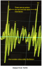
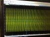
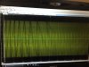
For Low Frequency Pickup, (Like listening to Heart Sounds) you can use a small Speaker as the Microphone.
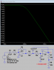
For Better Operation you need an Impedance Matching Transformer or a suitable transistor circuit. Use an "Emitter Follower".

http://chemelec.com/Projects/Spkr-Mic/Spkr-mic.htm
 
Last edited:
Please change the scale to see.


Your mic draws about 0.5mA so the voltage drop in the 1k +10k resistors is 5.5V then the mic gets 9V - 5.5V= 3.5V which is good for low level voices. There is a modification to an electret mic made by Linkwitz so that its Jfet is a follower instead of an amplifier. This modification is used when an electret mic gets a very high sound level inside a drum. Here is a video of the modification:


The input of your TL072 is biased at 0VDC and the signal causes it to drop as low as about -1.5V which is far from the -9V negative supply battery so it should be fine. The design of the TL072 is old and new ones use the same old design.


The Cmoy circuit uses one opamp in an OPA2134 to drive one 32 ohm earphone to a level not loud. You said you have a headset with 24 ohm earphones that make a load of 12 ohms when in mono and you want it loud. The OPA2134 does not produce enough output power to do it but the LM386 can do it easily.


Yes, so the waveform is not upside down. Here is your signal and one I found on the internet. I inverted your signal so it resembles the "normal" one:
Hey AG,
I've installed caps at the power supply as suggested. I don't see much progress. LM386 still clips
please see the attached pictures of scope.
1) TL072 is not clipping with r4=47k, you can see the scope output.
2) LM386 is the problem here, as it still clips....also by increasing the volume of lm386, sound gets bassy, making the heartsounds unclear.
here is a recording https://vocaroo.com/i/s117l0QLrEQt
3)after installing caps, raw mic signal is not too high anymore, see picture, also it shifted around 0.5v, it was around 5v before.

please suggest me another power amp replacement for lm386, with little higher input voltage range...also that doesn't get bassy.

Note:- i've not changed to non-inverting circuit yet. hope that doesn't affect.
 

Attachments

  • tl072_output.JPG
    tl072_output.JPG
    624.4 KB · Views: 209
  • raw_mic_output.JPG
    raw_mic_output.JPG
    550 KB · Views: 208
  • lm386_output.JPG
    lm386_output.JPG
    708.1 KB · Views: 203
Adding the capacitors should not have reduced the DC voltage on the mic to almost nothing. It was 5V before and it still should be 5V. With less than 2V on an electret mic it works very poorly and now yours shows a very low output level.
Your new 'scope photos still show a lot of high frequencies so maybe the lowpass filter is not working properly.
The new photos of the output of the TL072 and LM386 show strong 7 or 8 cycles per second (8Hz) and I wonder where that comes from (cardiac fibrillation?). Maybe it is motorboating oscillation in the circuit caused by poor connections on the solderless breadboard. A heartbeat is a pressure pulse, not a low frequency.

The LM386 with a 9V supply should be able to make very loud sounds in headphones without clipping that might deafen you. I just checked about headphones loudness on the web.
It says, "Take another moment and think about all those portable tape players. They sound great, and loud. Why, you can even hear them ten feet away as the teenage skateboarder that ran over your foot escapes. Power output? About 12 mW."
An LM386 with a 9V supply can produce deafening 140mW into one 32 ohms earphone without clipping. Maybe your +9V battery that is also powering the mic is dead?
 
Stethoscope-2.png

After Talking with you on the phone yesterday, This is What I would Recommend.
 
Last edited:
It is a good idea to use a separate battery for the preamp so that the current pulses of the power amp do not cause trouble with it.
 
Adding the capacitors should not have reduced the DC voltage on the mic to almost nothing. It was 5V before and it still should be 5V. With less than 2V on an electret mic it works very poorly and now yours shows a very low output level.
Your new 'scope photos still show a lot of high frequencies so maybe the lowpass filter is not working properly.
The new photos of the output of the TL072 and LM386 show strong 7 or 8 cycles per second (8Hz) and I wonder where that comes from (cardiac fibrillation?). Maybe it is motorboating oscillation in the circuit caused by poor connections on the solderless breadboard. A heartbeat is a pressure pulse, not a low frequency.

The LM386 with a 9V supply should be able to make very loud sounds in headphones without clipping that might deafen you. I just checked about headphones loudness on the web.
It says, "Take another moment and think about all those portable tape players. They sound great, and loud. Why, you can even hear them ten feet away as the teenage skateboarder that ran over your foot escapes. Power output? About 12 mW."
An LM386 with a 9V supply can produce deafening 140mW into one 32 ohms earphone without clipping. Maybe your +9V battery that is also powering the mic is dead?
Changes:- Changed new batteries. Also preamp and lm386 has now separate power supplies with common ground.
1)I don't understand something here, my voltage before R1(10k) is ~8.7V, after R1 it is showing 0.47V, so the voltage being supplied to mic is just 0.47V. what is happening with my circuit(tl072 gone)?
2) I've attached some scope outputs, raw mic output is very low
3) here is some recordings, for the scope output of lm386 following is the clipping recording. it shouldn't clip as per scope lm386 output is with in its range, but it still clips.why?
https://vocaroo.com/i/s10wca9kkqHx
4) sound output is very bassy, heart sounds are not clear due to bassy kinda output..please listen to the following recording.
https://vocaroo.com/i/s00STX7koXVa

I've no clue how you figured out that there are high frequencies in the output. but i double checked my low pass filter many times. its exactly as per your circuit
 

Attachments

  • lm386.JPG
    lm386.JPG
    626.8 KB · Views: 200
  • tl072.JPG
    tl072.JPG
    625.4 KB · Views: 202
  • raw_mic.JPG
    raw_mic.JPG
    583.4 KB · Views: 195
Last edited:
I assume your "R1" is the one on my schematic in post #22. I don't know your exact new battery voltage but if it is 9.2V then the 1k value for R16 has a current of (9.2V - 8.7V)/1k= 0.5mA which is normal for an electret mic.
Then since the mic voltage is only 0.47V the resistor R1 value is 8.7V - 0.47V)/0.5mA= 16460 ohms instead of 10k ohms.

Your output of the LM386 shows an average of +1.3V which is wrong. The capacitor C6 blocks DC so it should average 0V. The output pin 5 of the LM386 should be about +4.5V so maybe C6 is mounted with backwards polarity that would cause it to pass some of the DC. The output from the LM386 shows maximum peaks of only 1V does not show clipping and its output is far from a peak of 3V which would show clipping.

The outputs of the TL072 and LM386 still show plenty of 80Hz and high frequencies. A low frequency heartbeat signal has wide pulses. A high frequency "tick" or "snap" sound is narrow like your signals show.

Your recordings have a lot of things shuffling around but heartbeats sound like the normal pulses that I expect to hear. The internet is full of low frequency pulses from heartbeats.
Here is one with some murmurs:
And here is another:
Hey AG,
Both batteries used for tl072 are close to 9V. I've used R16=1kohm and R1=10 kohm, as per your circuit. Why is voltage across mic is 0.47V? What do you think is the issue here? do you think the opamp is gone?
"The outputs of the TL072 and LM386 still show plenty of 80Hz and high frequencies. A low frequency heartbeat signal has wide pulses. A high frequency "tick" or "snap" sound is narrow like your signals show."
80hz can be heart sound right? my cutoff frequency is 103hz, i don't understand why there are high frequencies still? I can hear heartsounds as well in the recordings, don't you?

is there a specific ratings for resistors or capacitors i use?
 
The voltage across the mic could be low if the polarity of C2 in my circuit is backwards. C2 does not conduct DC when it has the correct polarity then the opamp has nothing to do with it. Or replace C2 then replace the mic.
A heartbeat has no 80Hz sounds, instead it has wide pulses about two times to five times per second. Murmurs cause frequencies up to 103Hz or more. If the lowpass filter is made wrong then it could produce the 80Hz that is shown on your 'scope. 80Hz is a "boom", a heartbeat is a "THUMP thump".
Except for the things moving around your recordings sound fine.

Ordinary 1/8W or 1/4W resistors with a 5% tolerance and 5% metalized plastic film (not ceramic) for nF capacitors and electrolytic rated at 25V or more for higher value capacitors can be used.

Gary's circuit does not have a preamp since his lowpass filter has a gain of 1. The resistor that prevents destruction of your headphones and hearing reduce the output level a lot.
 
what do you mean another amplifier section? your circuit already has preamp and power amp right?

It has a "Low Pass Filter" and a "Power Amp".
The Low Pass Filter is Basically Unity Gain.
 
The voltage across the mic could be low if the polarity of C2 in my circuit is backwards. C2 does not conduct DC when it has the correct polarity then the opamp has nothing to do with it. Or replace C2 then replace the mic.
A heartbeat has no 80Hz sounds, instead it has wide pulses about two times to five times per second. Murmurs cause frequencies up to 103Hz or more. If the lowpass filter is made wrong then it could produce the 80Hz that is shown on your 'scope. 80Hz is a "boom", a heartbeat is a "THUMP thump".
Except for the things moving around your recordings sound fine.

Ordinary 1/8W or 1/4W resistors with a 5% tolerance and 5% metalized plastic film (not ceramic) for nF capacitors and electrolytic rated at 25V or more for higher value capacitors can be used.

Gary's circuit does not have a preamp since his lowpass filter has a gain of 1. The resistor that prevents destruction of your headphones and hearing reduce the output level a lot.
AG,
I figured out the voltage issue, mic was gone..replaced with new one, now it has high output like before, please see attached scope pictures.
The best (max gain without clipping) recording is below..please listen and that gain is not enough, i need lil more but lm386 clips. Also there is hiss due to lm386 and also breathing sounds. If i can eliminate those using some kinda bi-quad filters, gain might be sufficient since then i would only hear heart sound.
https://vocaroo.com/i/s102V2pftYfF

Experiment 2:-
Now I used a 3-wired ecm TSB140A, which has some jfet feature to capture loud sounds without clipping. It sounds little better and also it requres just 1.5V and look at raw mic output, its in mV. please see attached scope outputs for this mic setting
Also I have the best(max gain without clipping) recording with this mic as well. please listen to it below. It captures breathing and intestinal sounds along with lm386 hiss, if i can eliminate these the heartsound gain would be enough I guess. please advice onthis
https://vocaroo.com/i/s03M1lasJIaZ

EDIT:- I think lowpass is not working properly. Any idea why? i'm using exact same circuit
How about a audio codec (after preamp)with audio processing capability that can do FIR and Bi-quad filtering like TLV320AIC3100?
 

Attachments

  • lm386_tripple_supply_best.JPG
    lm386_tripple_supply_best.JPG
    545.7 KB · Views: 199
  • lm386_dual_supply _best.JPG
    lm386_dual_supply _best.JPG
    573 KB · Views: 192
  • tl072_dual_supply mic.JPG
    tl072_dual_supply mic.JPG
    695.2 KB · Views: 207
  • tripple suply_mic.JPG
    tripple suply_mic.JPG
    507.8 KB · Views: 187
  • tl072_tripple supply_mic.JPG
    tl072_tripple supply_mic.JPG
    666.1 KB · Views: 199
  • dual_supply_raw_mic.JPG
    dual_supply_raw_mic.JPG
    672.5 KB · Views: 193
Last edited:
Your latest output from the TL072 shows narrow pulses instead of normal wide low frequency heartbeats. It has a continuous 10Hz? (I can't see the 'scope timebase setting) fibrillation. The 'scope output from the LM386 has no heartbeats but instead has a continuous low frequency signal. The second recording sounds good.

I simulated my preamp and lowpass filter and they produce an excellent low frequency output. They show an expected gain and an expected cut of frequencies above 103Hz.

Your new mic has 3 wires so it has the Linkwitz modification for high sound levels.
 

Attachments

  • heartbeats.png
    heartbeats.png
    334.7 KB · Views: 201
  • lowpass filter.png
    lowpass filter.png
    22.4 KB · Views: 202
For various heart sounds, this site may be of interest.
 
Many of those defective heart sounds are caused by the patient listening to too much RAP!
 
Your latest output from the TL072 shows narrow pulses instead of normal wide low frequency heartbeats. It has a continuous 10Hz? (I can't see the 'scope timebase setting) fibrillation. The 'scope output from the LM386 has no heartbeats but instead has a continuous low frequency signal. The second recording sounds good.

I simulated my preamp and lowpass filter and they produce an excellent low frequency output. They show an expected gain and an expected cut of frequencies above 103Hz.

Your new mic has 3 wires so it has the Linkwitz modification for high sound levels.
AG,
I see your simulation. its looks as it should be. but I've exact same circuit except for r2=2.2k in my circuit and i know it doesn't have any effect on low pass. Do you have any idea why my low pass is behaving that way?
"The 'scope output from the LM386 has no heartbeats but instead has a continuous low frequency signal." what do you mean? i'm hearing heart sounds though.
 
Maybe it is your 'scope that is cutting low frequencies because they sound good. The scope output of the LM386 does not show heartbeat pulses and does not even show the high amplitude narrow pulses from the TL072 and I do not know why.
 
Maybe it is your 'scope that is cutting low frequencies because they sound good. The scope output of the LM386 does not show heartbeat pulses and does not even show the high amplitude narrow pulses from the TL072 and I do not know why.
Hey AG,
i've attached scope output for a sinewave generated and sent through preamp and lowpass. I've used 90HZ and 1000HZ
1000HZ:
raw input sinewave has higher voltage reading than preamp output...does that mean lowpass filter is attenuating higher frequencies than 103hz but not reducing enough?
look at the scope otputs taken at following points.
1.at just before c2
2.just after R5
3. at pin 7 of tl072.

90HZ:
there is voltage gain after preamp for this case.
so why my lowpass filter is behaving this way?
 

Attachments

  • 90hz_lowpass_output.JPG
    90hz_lowpass_output.JPG
    939 KB · Views: 198
  • 90hz_preamp_output.JPG
    90hz_preamp_output.JPG
    887.1 KB · Views: 195
  • 90hz_raw_input.JPG
    90hz_raw_input.JPG
    642.4 KB · Views: 198
  • 1000hz_lowpass_output.JPG
    1000hz_lowpass_output.JPG
    559.9 KB · Views: 192
  • 1000hz_preamp_output.JPG
    1000hz_preamp_output.JPG
    582.6 KB · Views: 187
  • 1000hz_raw_input.JPG
    1000hz_raw_input.JPG
    566.5 KB · Views: 198
Status
Not open for further replies.

Latest threads

New Articles From Microcontroller Tips

Back
Top