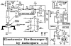
Continue to Site

Welcome to our site!

Electro Tech is an online community (with over 170,000 members) who enjoy talking about and building electronic circuits, projects and gadgets. To participate you need to register. Registration is free. Click here to register now.

  • Welcome to our site! Electro Tech is an online community (with over 170,000 members) who enjoy talking about and building electronic circuits, projects and gadgets. To participate you need to register. Registration is free. Click here to register now.

Electronic Stethoscope, Electret condenser mic distortion issues

Status
Not open for further replies.
hello colin, thanks for replying

were you talking about the 2.2k in the tl071 circuit? if i increase the resistor value from 2.2k to 22k the gain drops drastically right? correct me if i'm wrong
The TL071 circuit has a 100k gain control labeled VOL. With the 100k trimpot set to 100k then the gain is 1+ (100k/2.2k)= 46.5 times which is good when you talk in a normal conversation level about 5cm away from the mic. With the trimpot set at half rotation then the gain is 23.7 times and you would need to talk a little louder or hold the mic closer to your mouth. With the trimpot turned down all the way then the gain is only 1 and if you scream very close to the mic then you might not be heard. Then why change the 2.2k to 22k??

ANY amplifier will clip if its input signal level is too much causes the output to try to go higher than is possible. An LM386 has a gain of 20 times but it can be 200 times if a capacitor is added between pin 1 and pin 8.
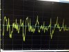
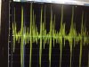
Your recordings had some very loud sounds like you were rubbing the mic in your hand or scraping the mic on the floor. When I hold my mic mounted in a lid on my chest then it does not move and does not produce those noises.

A piezo transducer picks up vibrations like from a guitar, piano or car engine. It makes a poor microphone.
AG,
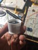
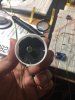
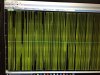
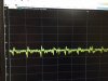
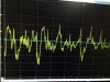
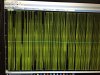
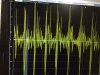
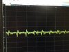
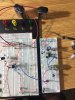
If you look at the picture, my mic is not in contact with the chest piece, but as you said it pics up the rubbing on the diaphragm pretty louder. but why is it not picking up heartsounds? that's my question. both rubbing and heart sounds are produced from the same distance from the mic. it doesn't clip with rubbings or movement but its clipping the heartsounds when i put the chest piece on my chest. can you reason with that? do you think low frequencies are getting clipped?

Also can you show your chest piece in the jar lid? it would be of great help.
 
I fixed an electronic stethoscope circuit when somebody posted it on a forum and said the original circuit didn't work. I built one and used it a few times 13 years ago. It is long gone.
Here is the schematic from my files showing a sketch of how the mic was mounted in a lid:
 

Attachments

  • Electronic_Stethoscope_2 schematic.png
    Electronic_Stethoscope_2 schematic.png
    7.3 KB · Views: 307
I fixed an electronic stethoscope circuit when somebody posted it on a forum and said the original circuit didn't work. I built one and used it a few times 13 years ago. It is long gone.
Here is the schematic from my files showing a sketch of how the mic was mounted in a lid:
AG,

so is the top side or top surface of the lid is your diaphragm ?? and you put mic in the lid and sealed the other side of lid??
 
The hollow concave part of the plastic lid has my microphone opening. The rim of the lid is against the patient's skin above the heart. The microphone does not touch the skin. The mic is sealed in the lid and no sounds can enter where the cable exits.
 
The hollow concave part of the plastic lid has my microphone opening. The rim of the lid is against the patient's skin above the heart. The microphone does not touch the skin. The mic is sealed in the lid and no sounds can enter where the cable exits.
Hi AG,

I really appreciate your replies. I'm little surprised how a hollow opening with out a chest piece diaphragm can produce sound waves of heartbeat for the mic to capture? isn't that the sole reason or purpose of a diaphragm on the stethoscope chest piece?
 
Maybe the patient's skin is the diaphragm under my lid?
If I put an ear against the skin above the heart without a diaphragm then I hear the heartbeat the same.
 
Maybe the patient's skin is the diaphragm under my lid?
If I put an ear against the skin above the heart without a diaphragm then I hear the heartbeat the same.
hi AG,
I tried your circuit. is this how you suggested? it doesn't pick the sound.
i tried with steth chestpiece by placing the mic in a tube and bringing the tube close to the chestpiece outlet, i can heart sound a bit but lm386 clips after like 10-15% knob roration
 

Attachments

  • IMG_4983.JPG
    IMG_4983.JPG
    244.7 KB · Views: 225
  • IMG_4982.JPG
    IMG_4982.JPG
    229.4 KB · Views: 236
Maybe your electret mic does not pickup low frequencies. How does it sound when you speak to the mic?
 
Maybe your electret mic does not pickup low frequencies. How does it sound when you speak to the mic?
here are some useful oscilloscope outputs, ive attached the pics
1)raw mic heart signal, with mic behind the cup setup (not behind stethoscope chestpiece)----signal shows reading goes almost 0.4v (which is max input signal voltage for lm386)
2)tl072 output (before going to lm386) signal reading shows for mic behind cup setup, almost going over 2.5 volts peak.(which is way beyond lm386 input voltage)
3) similarly i've readings of raw mic signal and signal after tl072 for mic behind chest piece, they are way out.take a look

now i'm totally puzzled how ppl have pulled it through with ECM with the circuit you have designed (I've seen ppl on different forums reporting success with your circuit...seems like i'm the unlucky one). as my raw signal itself is way off. do you think my mic is too sensitive and doesn't serve the purpose? please advice. if you have a different ecm mic or different opamps on mind. I'm totally ok to tryout expensive opamps instead, if you think of any replacement.

Edit:- Mic i'm using http://d.digikey.com/lYXup000NLmg8K0710p0z0S.
 

Attachments

  • raw_mic_signal_mic_behind_steth_chestpiece.JPG
    raw_mic_signal_mic_behind_steth_chestpiece.JPG
    93.5 KB · Views: 192
  • tl072_output_mic_behind_steth_chespiece.JPG
    tl072_output_mic_behind_steth_chespiece.JPG
    140.6 KB · Views: 210
  • tl072_output_mic_behind_cup_setup.JPG
    tl072_output_mic_behind_cup_setup.JPG
    115.3 KB · Views: 198
  • raw_mic_signal_cup_setup.JPG
    raw_mic_signal_cup_setup.JPG
    81.2 KB · Views: 203
Last edited:
Your TL072 shows a lot of high frequencies that should be filtered out. Maybe the lowpass filter is wrongly made into a highpass filter.

The LM386 has a gain of 20 times. Its datasheet shows a graph that with a 9V supply (but your battery voltage might drop on the current peaks) its maximum output is 3.2V peak into 16 ohms (two 32 ohms earphones in parallel) so its input must never be more than 3.2V/20= 0.16V peak, or less if your battery voltage sags.

The levels at the output of the TL072 are way too high so of course the TL072 and the LM386 are clipping. Turn down the gain.

All Omni electret mics looking like the one you got from Digikey have almost the same output level and frequency response. I have a smaller one from a cell phone with an output level a little less.
Most audio opamps work the same in that simple circuit.
mine was uni- directional mic.
would you recommend opa2134 instead lm386? lm386 is clipping right away with tl072 circuit you recommended and ecm mic. i decreased gain by decreasing the resistor value down in tl072 circuit but it didn't help, and more over i need good gain, heart sounds have to be loud period. I will be only using earphones, no speakers.
So please advice a better audio amplifying circuit.
 
Last edited:
I saw the first mic part number for the Omni mic you used. I did not notice that now you are using a different Uni mic.
I cannot read the tiny fuzzy numbers on your 'scope screen because you saved them as fuzzy JPG file type instead of very clear PNG file type.

A mic sensitivity is rated with a loud 94dB sinewave at a certain distance of 10cm I think. The reference is 1V so your new Uni mic with a sensitivity of -46dB will produce an output of 1V/200= 5mV.
The voltage gain of the first opamp in my circuit is R4/(R2 + Rmic)= 47k/4.4k= 10.7 times. Then a loud 94dB sound at 10cm will produce an output of 5mV x 10.7= 53.5mV (0.0535V). The voltage gain of the lowpass filter opamp is 1.6 times so the output to the volume control will be 85.6mV.

The LM386 has a gain of 20 so its output will be 1.7V RMS or have peaks of 2.4VC with the volume control at maximum . Then the output will not be clipping if the battery is more than 8V. Typo is fixed.

The LM386 clips at 2.65V RMS when powered by 9.0V and has a 16 ohm load. Then the power in the load is 2.65V squared/16= 439mW. Each earphone will get half at 220mW which will deafen you sine 100mW is extremely loud in headphones.
If the mic picks up a very loud heartbeat then the mic and/or the opamps will clip. You did not say which resistor you decreased.

Low frequencies look smooth on a 'scope. Your mic output looks smooth but the output of your preamp is full of clipping and high frequency peaks.

I see a solderless breadboard and a mic with a built-in preamp on your photos. The solderless breadboard causes all kinds of interference and oscillation in high gain circuits like this.

An LM386 is a power amplifier that can drive a speaker or any kind of headphones. An OPA2134 is an opamp that has very low output power like most opamps and cannot drive many kinds of headphones. There is a volume control in between the opamp and the power amp that stops the power amp from clipping when it is turned down. It should be able to turn down the output level to zero. But maybe your solderless breadboard is causing oscillation and then the volume control acts like an on-off switch.
 
Last edited:
H AG,
I apologize for the unclear pics, i attached better ones please take a look.
1)raw mic output is not in mV as you calculated its turning out to be around 0.4V and nothing loud input i'm giving, just heartbeats using cup setup as you recommended or steth chest piece.
2) yes i was changing r4 value...went down till 4.7k , but no use. still clips right away.
3) i'm not sure if preamp is clipping, it could be that scope y-axis setting it looks like clipping. when i turndown lm386 down almost completely i can hear heartsounds without clipping (but very feeble at aortic area of heart). but lm386 clips like crazy even if i turn it on even a little.
4)i'm not gonna need too much power since i'm not gonna use big headphones or anything like that. just small inear- earphones, that's it. I saw that opa2134 has wide input signal range as -vcc-0.7 to +vcc-0.7, so hopefully it doesn't clip in this case.also 386 makes lil hiss it seems. looking to develop a sophisticated steth with great heart sounds.
5) the builin preamp mic on breadboard is not connected to any powersource. i just pinned it there so that i don't lose it. my circuit is only power with supply. i've attached a pic of complete circuit on breadboard. please take a look.

EDIT: FYI, I've not used the 1000uf and 470uf capacitors in parallel to batteries in making dual supply. i made it without capacitors.
 

Attachments

  • raw_mic_signal_mic_behind_steth_chestpiece (2).JPG
    raw_mic_signal_mic_behind_steth_chestpiece (2).JPG
    635.3 KB · Views: 207
  • tl072_output_mic_behind_steth_chespiece (2).JPG
    tl072_output_mic_behind_steth_chespiece (2).JPG
    999.1 KB · Views: 206
  • tl072_output_mic_behind_cup_setup (2).JPG
    tl072_output_mic_behind_cup_setup (2).JPG
    739.8 KB · Views: 205
  • raw_mic_signal_cup_setup (2).JPG
    raw_mic_signal_cup_setup (2).JPG
    562.7 KB · Views: 212
  • IMG_4990.JPG
    IMG_4990.JPG
    471.1 KB · Views: 229
Last edited:
I am amazed that your raw mic produces heartbeat peaks as high as 1.5V.
With R4 at 4.7k then the first preamp has a gain of 4.7k/(2.2k + 2.2k)= 1.07 times and the second opamp's gain of 1.6 has an output of 2.57V peak which is far from clipping but yours shows severe clipping.
Wait a minute! Your clear photos show the output of the TL072 clipping with an output of only 2.5V peak. It should clip at about 8V peak with the plus and minus 9V supply. Why is it clipping with such a low peak output voltage? Maybe the battery voltages are sagging with signal level since you did not install the 470uF and 1000uF supply bypass capacitors.

I forgot to say that the old TL07x opamps have a problem where if an input voltage becomes within a few voltage from the negative supply then the output suddenly goes as positive as it can go which might be happening. The OPA2134 does not have this problem. But the OPA2134 cannot drive most headphones or earphones if they are the normal 32 ohms, a power amp like the LM386 is needed to drive them.

I am sorry that the first opamp inverts the signal, that is how the original defective circuit was designed and I did not change it. Doctors are probably used to seeing non-inverted heartbeats.
Hey AG,
1)I think preamp wasn't clipping, its just that output reading doesn't fit scope y-axis scale on monitor so its showing flat at top. if i fix scale it might not happen. Anyways I'll try to install the caps and see if there is any progress.
2)yes that was my issue here why my raw mic is outputting so high voltage reading. and i'm using +9v of supply to power up the mic, that's how it should be right? or do i need to use a lower power supply?fyi my mic can stand 2v-10v.
3) but my input voltage from mic is around 5v right?, not with in few voltage from -ve supply voltage? how can I get new TL07X opamps? i just bought what is available on digikey.
4)I was looking to replace lm386 with opa2134, but are you suggesting opa2134 for tl072? but if i do so can i be able to have lowpass filter and preamp with it, like what you did with tl072?
5)what's your take on cmoy https://tangentsoft.net/audio/cmoy/ . It says it can drive both low impedance and high impedence. FYI earphones i'm gonna use are not going to be around 32ohms or less, lets say apple earphones has 24ohms.

"I am sorry that the first opamp inverts the signal, that is how the original defective circuit was designed and I did not change it. Doctors are probably used to seeing non-inverted heartbeats."
6)are you recommending me to try non-inverting circuit with tl072? if so can you provide me a right schematic to try?. Thanks

 
"A piezo transducer picks up vibrations like from a guitar, piano or car engine. It makes a poor microphone."

How wrong you are. You don't know what you are talking about.

I use a piezo on a window and the result is just like you have removed the sheet of glass. I have sold 30,000 "wall bugs" to those who want to listen to people in a room. The result is PERFECT. Don't make comments about things you know nothing about.
 
A piezo transducer resonates at about 4kHz to 5kHz and at other frequencies. That is why it is made into a beeper.
I think a window glass also resonates at some frequency.
They resonate because they are stiff. Therefore they make poor microphones but are good at sensing vibrations.
A piezo transducer senses "knock" vibrations in a car engine. It also senses vibrations in a drum and in a piano. They are vibration sensors, not microphones.

Here is how to change the preamp to be non-inverting:
 

Attachments

  • opamp inverting and non-inverting.png
    opamp inverting and non-inverting.png
    10 KB · Views: 236
A piezo transducer resonates at about 4kHz to 5kHz and at other frequencies. That is why it is made into a beeper.
I think a window glass also resonates at some frequency.
They resonate because they are stiff. Therefore they make poor microphones but are good at sensing vibrations.
A piezo transducer senses "knock" vibrations in a car engine. It also senses vibrations in a drum and in a piano. They are vibration sensors, not microphones.

Here is how to change the preamp to be non-inverting:
Hi AG,
could you also answer my other questions in my above post?
 
"A piezo transducer picks up vibrations like from a guitar, piano or car engine. It makes a poor microphone."

How wrong you are. You don't know what you are talking about.

I use a piezo on a window and the result is just like you have removed the sheet of glass. I have sold 30,000 "wall bugs" to those who want to listen to people in a room. The result is PERFECT. Don't make comments about things you know nothing about.
hello colin,
I do agree piezo sensors are good for vibration detection, and they do work in detecting heart sounds. but they aren't loud enough as i'm expecting. i've already worked on cm01b piezo sensor before switching to ECM. Literature and research papers are suggesting ECM and MEMS microphones for stethoscope over piezo.
 
1)I think preamp wasn't clipping, its just that output reading doesn't fit scope y-axis scale on monitor so its showing flat at top. if i fix scale it might not happen. Anyways I'll try to install the caps and see if there is any progress.
Please change the scale to see.

2)i'm using +9v of supply to power up the mic, that's how it should be right? or do i need to use a lower power supply? fyi my mic can stand 2v-10v.
Your mic draws about 0.5mA so the voltage drop in the 1k +10k resistors is 5.5V then the mic gets 9V - 5.5V= 3.5V which is good for low level voices. There is a modification to an electret mic made by Linkwitz so that its Jfet is a follower instead of an amplifier. This modification is used when an electret mic gets a very high sound level inside a drum. Here is a video of the modification:

3) but my input voltage from mic is around 5v right?, not with in few voltage from -ve supply voltage? how can I get new TL07X opamps?
The input of your TL072 is biased at 0VDC and the signal causes it to drop as low as about -1.5V which is far from the -9V negative supply battery so it should be fine. The design of the TL072 is old and new ones use the same old design.

4)I was looking to replace lm386 with opa2134, but are you suggesting opa2134 for tl072? but if i do so can i be able to have lowpass filter and preamp with it, like what you did with tl072?
5)what's your take on cmoy https://tangentsoft.net/audio/cmoy/ . It says it can drive both low impedance and high impedence. FYI earphones i'm gonna use are not going to be around 32ohms or less, lets say apple earphones has 24ohms.
The Cmoy circuit uses one opamp in an OPA2134 to drive one 32 ohm earphone to a level not loud. You said you have a headset with 24 ohm earphones that make a load of 12 ohms when in mono and you want it loud. The OPA2134 does not produce enough output power to do it but the LM386 can do it easily.

6)are you recommending me to try non-inverting circuit with tl072? if so can you provide me a right schematic to try?
Yes, so the waveform is not upside down. Here is your signal and one I found on the internet. I inverted your signal so it resembles the "normal" one:
 

Attachments

  • stethoscope signals.png
    stethoscope signals.png
    764.7 KB · Views: 229
Status
Not open for further replies.

Latest threads

New Articles From Microcontroller Tips

Back
Top