Continue to Site

Welcome to our site!

Electro Tech is an online community (with over 170,000 members) who enjoy talking about and building electronic circuits, projects and gadgets. To participate you need to register. Registration is free. Click here to register now.

  • Welcome to our site! Electro Tech is an online community (with over 170,000 members) who enjoy talking about and building electronic circuits, projects and gadgets. To participate you need to register. Registration is free. Click here to register now.

Electronic Stethoscope, Electret condenser mic distortion issues

Status
Not open for further replies.
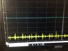
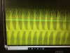
For 'calibration' purposes, how about using the Generate\Chirp function of Audacity to record a constant-amplitude frequency sweep, play that back through a good quality speaker, and record the sound as picked up by your mic and preamp? That should give you a reasonably good comparative indication of the frequency response of your setup (albeit modified by the frequency response of the speaker and its driver).
 
There is no "good quality speaker" and an anechoic chamber available with a flat enough response. I measured the response of speakers outdoors with the speaker system lying on the ground pointing straight up to the microphone hanging from a tree branch. Even pretty good speakers needed equalization.

A modern electret mic has a very flat frequency response even cheap ones. Headphones are easy to measure their response. The electronics are also easy to measure their response which should be a perfectly straight line.
 
Even pretty good speakers needed equalization.
Granted, but presumably their response isn't as spikey as the TS seems to be finding with his setup?
 
Before you used headphones but now you are using a speaker ? How do you prevent acoustical feedback howling?
Oh, you record it then play it back later on the speaker with the stethoscope circuit turned off.
 
Before you used headphones but now you are using a speaker ? How do you prevent acoustical feedback howling?
Oh, you record it then play it back later on the speaker with the stethoscope circuit turned off.
hey john,
i tried the opa2134 circuit is making complete distortion clipping...i checked scope outputs at intersection of r5 and r6 with c3 in place and without c3. do you thing wrong capacitor value, usng c3&c4 =47nf. take a look at the attachments
 

Attachments

  • without c3.JPG
    without c3.JPG
    583.8 KB · Views: 201
  • with c3.JPG
    with c3.JPG
    965.2 KB · Views: 202
You are not supposed to look at the junction of R5, R6 and C3 because it is in the middle of the lowpass filter circuit. It looks like a single order filter. Removing C3 makes a single order lowpass filter with a 45Hz -3dB cutoff.

My filter is a normal Sallen Key second order Butterworth lowpass filter with a cutoff frequency of 103Hz. The gain of 1.589 times by R7 and R8 is extremely important to make a Butterworth response. When the gain is a little more than 1.6 then there is a peak at 103Hz and if the gain is 3 or more then the filter oscillates at 103Hz. What are your R7 and R8 values?
33k and 56k

Never mind, its working fine....Thank you.
would you add a resister connecting the input to lm386 on one end and other end to ground, to make the 2nd high pass filter with 1.5uf cap?
 
Last edited:
The LM386 already has a 50k resistor to ground inside it at each input. Then use a series capacitor to cut low frequency heartbeat sounds if you want.
 
The 50k ohms input of the LM386 parallel with the 20k volume control makes 14.3k that the capacitor drives. 1.5uF produces a low frequency cutoff at 7.5Hz and 150nF produces 75Hz.
 
The 50k ohms input of the LM386 parallel with the 20k volume control makes 14.3k that the capacitor drives. 1.5uF produces a low frequency cutoff at 7.5Hz and 150nF produces 75Hz.
Hi john, i'm using opa2134 single 9v supply circuit with lm386 to drive my earphones.(in reference to the inbox message)
 
"This is not your thread so I cannot lookup which opamp you use to drive your headphones and the impedance of each earphone. If the headphones are 32 ohms per ear then most opamps are overloaded if they try to drive two 32 ohms earphones in parallel."
 
Hi john,
I'm implementing partly analog and partly dsp. i'm gonna have a preamp and anti-aliasing filter ,low pass about 1500hz. and then some advanced dsp filters. I'm gonna try opa335 for preamp and low pass, do you have any better dual opamp recommendation?
limitation: Supply voltage 3.7V
Mic: ECM
Thanks in advance.
 
I don't know what "rather sending money on paypal in advance" means.

Mike.
This means you send the money in advance, this allows you to pay for the bits so your factory can build one. Funny a device designed and aimed at Doctors, is then sold to them in a way that they cant/dont pay by. Doctors like many businesses expect 28 day invoices, if your selling 3000 or 30,000 units you can accommodate your target audience.

BTW midwives use a unit that picks up a babys heart beat and the umbilical cord blood flow, they cost around £50.

How many valves/tubes did you squeeze in yours colin?
 
Replying to your conversation where I could not attach anything:
A filter response test is made with a sinewave input that sweeps the frequencies with a constant input level.
I do not know why the Litmann recording has so many sharp sounds and I do not know why the frequency graphs have a linear horizontal frequencies instead of the normal logarithmic.
Here is the schematic modified for using a single 9V battery:

sir can u send output graphs for these modified circuit
 
Status
Not open for further replies.

Latest threads

New Articles From Microcontroller Tips

Back
Top